Table 5-17 Rectier for operation on single-phase AC with electrical connection via connection
terminal (5.2)
Type Method Rated input voltage
range
U
1
AC (40...60Hz)
Output voltage
U
2
DC
Max. output current
I DC
V V R load
A
L load
A
32 07332B40 Half-
wave
0 ... 500 (±10%) U
1
·0.445 1.6 2.0
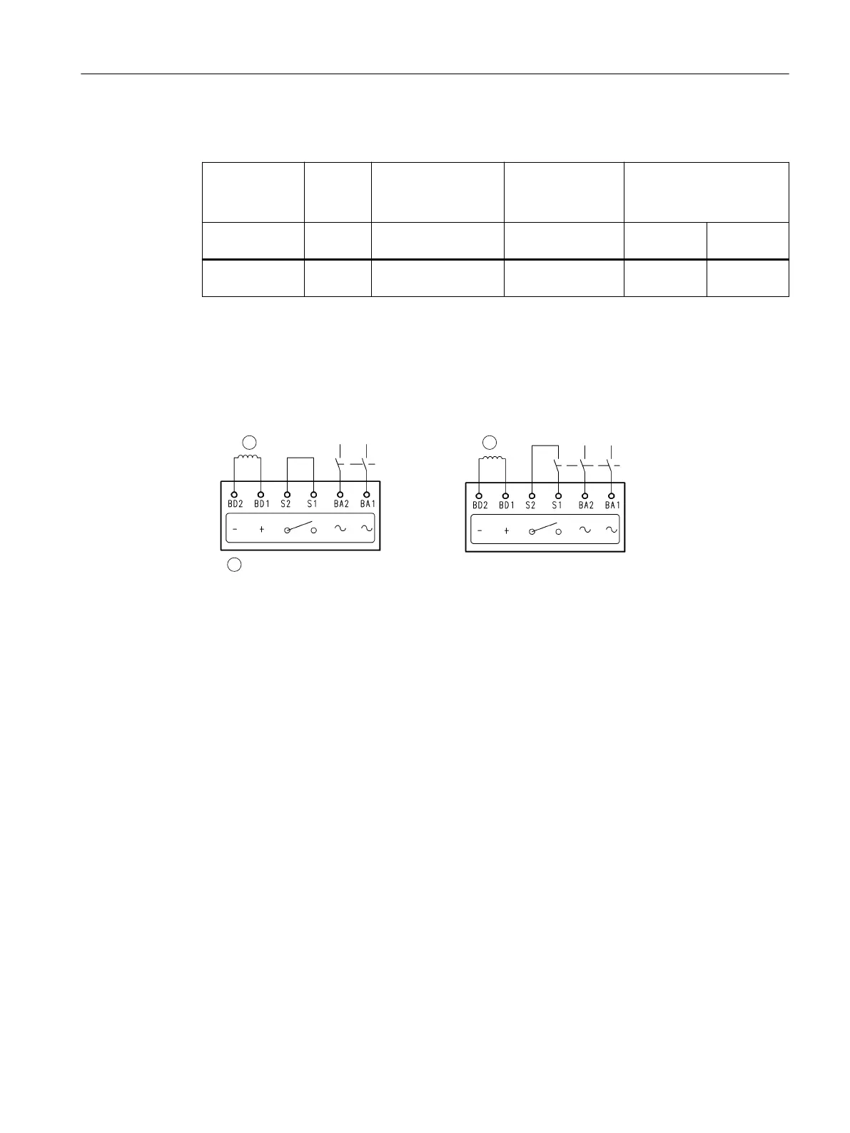
Brakes with integrated rectiers are either equipped with a half-wave rectier or with a
rectier bridge.
By appropriately connecting the integrated rectier, you switch between AC (normal
interlocking time t
1
) or DC (short interlocking time t
1
).
11
1
1RUPDOLQWHUORFNLQJWLPHW6KRUWHQHGLQWHUORFNLQJWLPHW
%UDNHZLQGLQJ:LWK'&VLGHVZLWFKLQJ
$&VLGHVZLWFKLQJ
PXVWDOVREHSHUIRUPHG
Figure5-7 Pin assignment of the rectier
Voltage ripples caused by switched-mode power supplies can cause humming or unintended
behavior of the component depending on the size and torque.
The user or the system manufacturer has to ensure proper operation by means of the
electrical control.
Motor components and options
5.2Options
1PH8 SIMOTICS M main motors
Conguration Manual, 12/2022, A5E51895839A 189

 Loading...


