EasyManuals Logo

Siemens SINAMICS V10 User Manual

Siemens SINAMICS V10
124 pages
To Next Page IconTo Next Page
To Previous Page IconTo Previous Page
Page #119 background imageLoading...
Page #119 background image
Replacing the fans
A
There are two fans preassembled on Frame Size B, Frame Size C and Frame Size D
respectively. When replacing the fan, proceed the procedure shown below.
Removing the fans from Frame Size B
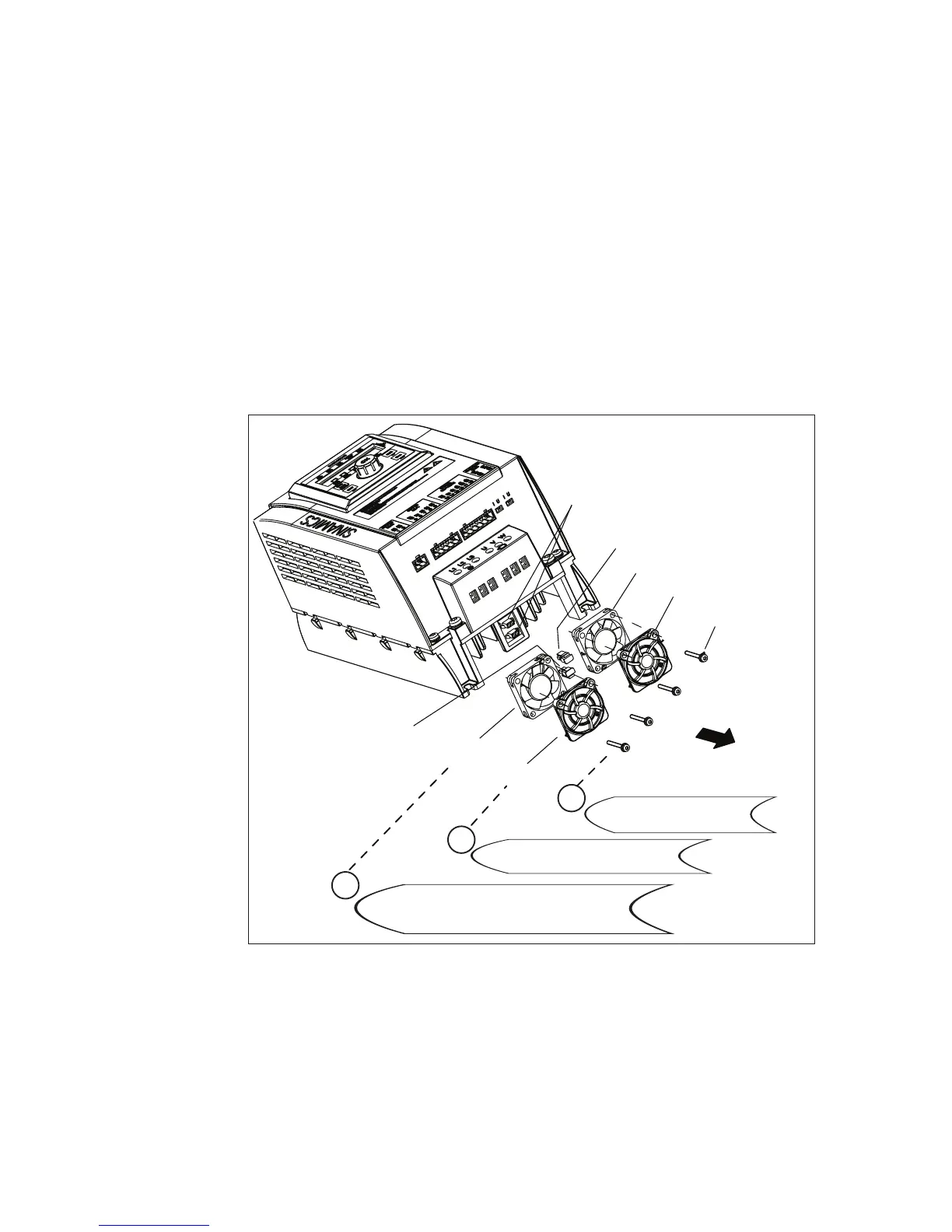
Follow the steps described in the figure to remove the fans from Frame Size B:
Fan
Fan cover
Fan cover
Fan
Connector on the fan
Connectors on inverter housing
Connector
on the fan
4 M3 mounting screws
(Tightening torque: 0.8 Nm)
Frame Size B
Remove the fan covers from the fans.
2
1
Remove the mounting screws
from the fan covers.
Remove the fans from the inverter by manually
detaching connectors on the fans from mating
connectors on the housing.
3
Figure A-1 Removing the fans from Frame Size B
SINAMICS V10
Operating Instructions, 08/2011, A5E03453178 (this is not an order number) 119

Table of Contents

Questions and Answers:

Question and Answer IconNeed help?

Do you have a question about the Siemens SINAMICS V10 and is the answer not in the manual?

Siemens SINAMICS V10 Specifications

General IconGeneral
Control MethodV/f control
Degree of protectionIP20
Relative Humidity5 % to 95 % (non-condensing)
AltitudeUp to 1000 m above sea level without derating
Frequency50 Hz / 60 Hz
ProtectionOvercurrent, overvoltage, undervoltage, overload, short circuit, ground fault
CommunicationRS485
Operating Temperature-10°C to +50°C
Power Range0.37 kW to 4 kW
Storage Temperature+70 °C
Input Voltage1-phase: 200-240V AC, 3-phase: 380-480V AC

Related product manuals