Programming and Operating Manual (Milling)
94 6FC5398-4DP10-0BA6, 09/2017
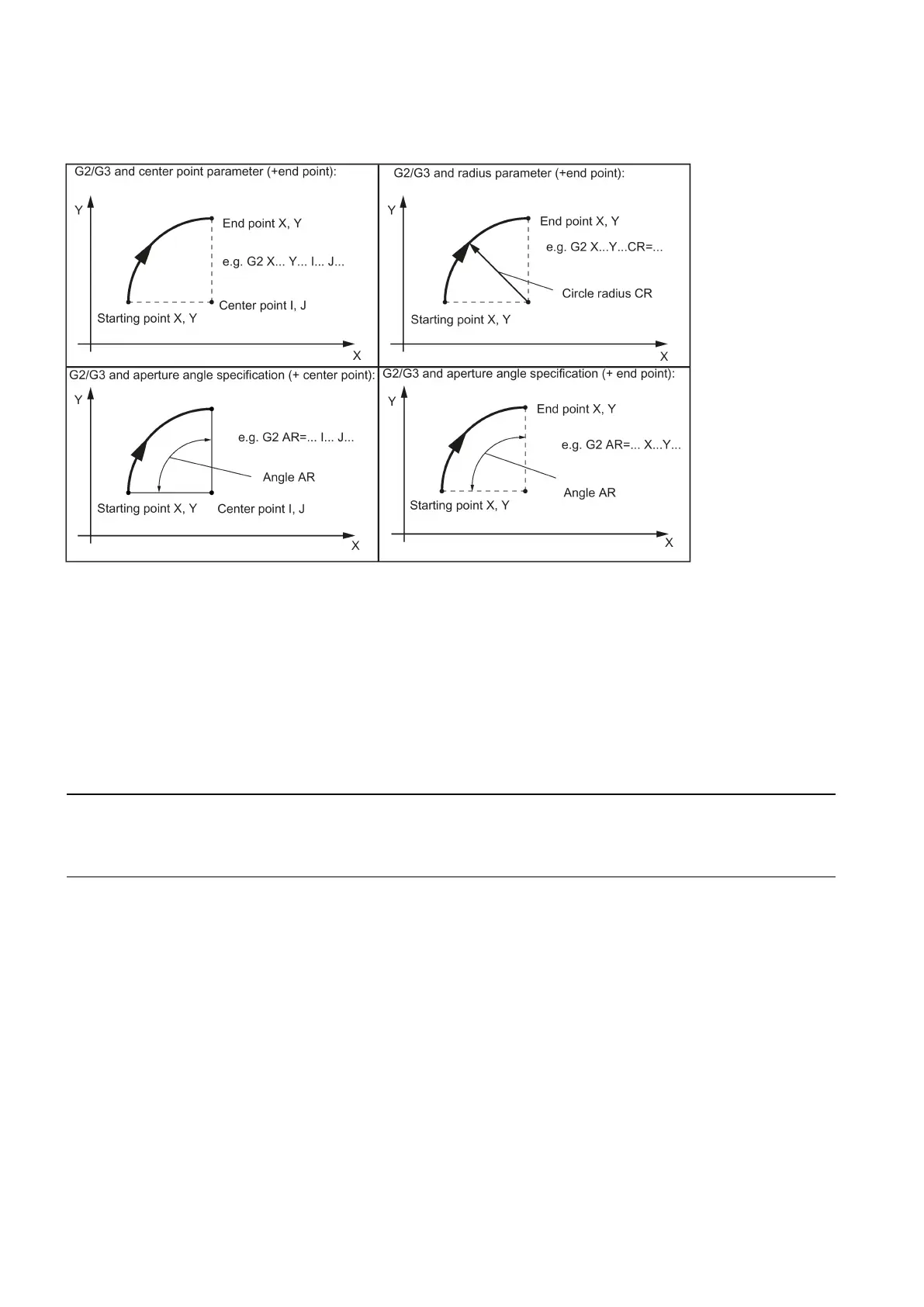
The description of the desired circle can be given in various ways:
See the following illustration for possibilities of circle programming with G2/G3 using the example of the axes X/Y and G2:
G2/G3 remains active until canceled by another instruction from this G group (G0, G1, ...).
The
is determined by the programmed
.
G2/G3 X... Y... I... J...
; End point and center point
; Circle radius and end point
; Opening angle and center point
; Opening angle and end point
; Polar coordinates, circle around the pole
Note
Other circle programming
instructions:
CT - circle with tangential connection
• CIP - circle via intermediate point (see following sections)
Input tolerances for the circle
Circles are only accepted by the control system with a certain dimensional tolerance. The circle radius at the starting and
end points are compared here. If the difference is within the tolerance, the center point is exactly set internally. Otherwise,
an alarm message is issued.
in a block are only possible if the center point and the end point are specified.
For circles with radius specification, the arithmetic sign of CR=... is used to select the correct circle. It is possible to program
two circles with the same starting and end points, as well as with the same radius and the same direction. The negative sign
in front of CR=
... determines the circle whose circle segment is greater than a semi-circle; otherwise, the circle with the
circle segment is less than or equal to the semi-circle and determined as follows:

 Loading...


