( (QFRGHU
0 0RWRU
6HQVRU0RGXOH
QRWDSSOLFDEOHIRUPRWRUZLWK
'5,9(&/L4LQWHUIDFH
'5,9(&/L4
(
(
0
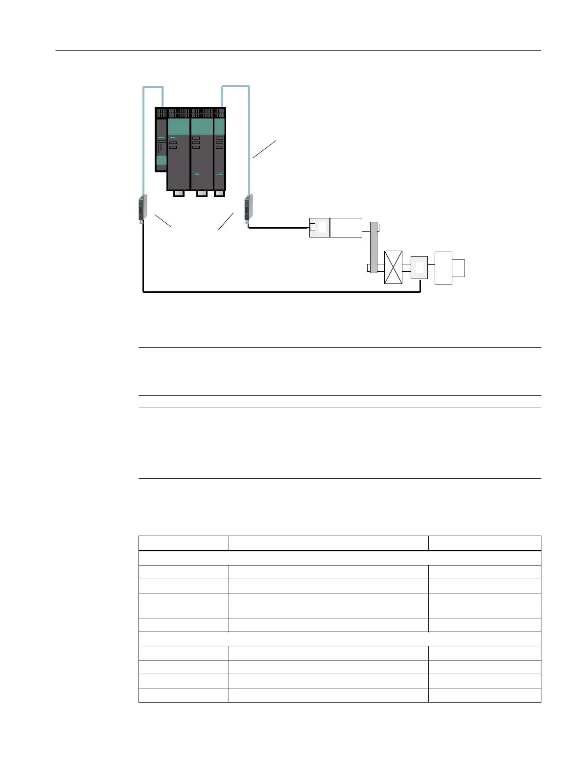
Figure 4-30 Example of a 2-encoder system on a rotary axis
When parameterizing a 2-encoder system with Safety Integrated, you must align parameters
p9315 to p9329 with parameters r0401 to r0474.
Note
Assignment of the encoder parameters
Parameters p95xx are assigned to the 1st encoder; parameters p93xx to the 2nd encoder.
Note
Transfer of the values from the encoder commissioning
To accept the values from the parameters filled during the encoder commissioning to the safety
parameterization, set parameter p9700 = 46 (2E hex). This copy function is only possible if you
are connected online with the drive unit.
Table 4-6 Encoder parameters and corresponding safety parameters for 2-encoder systems
Safety parameters Designation Encoder parameters
p9315/p9515 SI Motion coarse position value configuration
p9315.0/p9515.0 Up-counter r0474[x].0
p9315.1/p9515.1 Encoder CRC, least significant byte first r0474[x].1
p9315.2/p9515.2 Redundant coarse position value, most significant
bit left-justified
r0474[x].2
p9315.16/p9515.16 DRIVE-CLiQ encoder p0404[x].10
p9316/p9516 SI Motion encoder configuration, safety functions
p9316.0/p9516.0 Motor encoder, rotary/linear p0404[x].0
p9316.1/p9516.1 Actual position value, sign change p0410[x]
p9317/p9517 SI Motion linear scale grid division p0407
p9318/p9518 SI Motion encoder pulses per revolution p0408
Safety functions integrated in the drive
4.19 Safe actual value acquisition
Safety Integrated (with SINAMICS S120)
Commissioning Manual, 02/2020, A5E46305916B AB 193