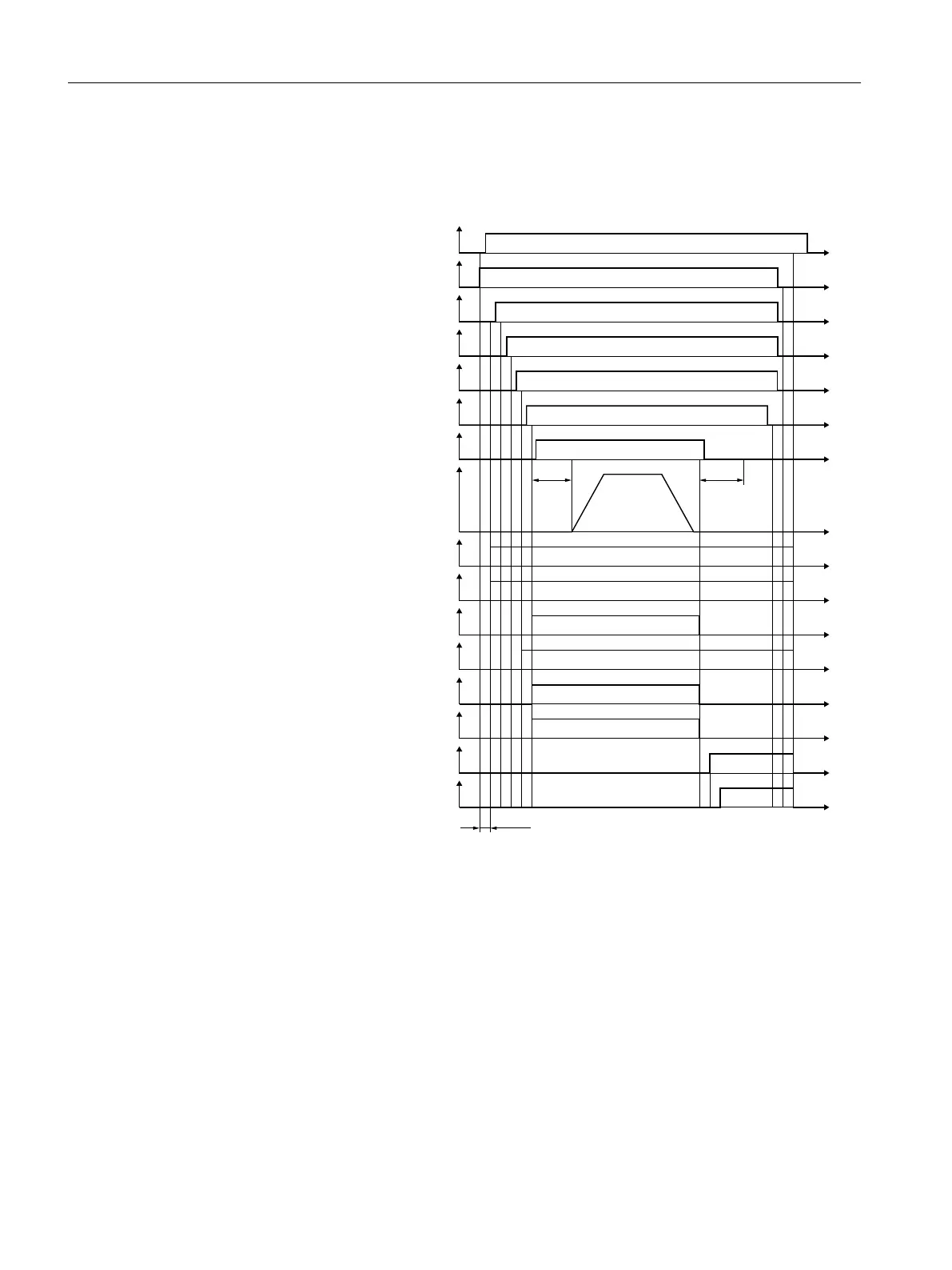
Test of an external brake
The following figure shows the communication via SIC and SCC during the test of an external
brake:
6HOHFWEUDNHWHVW
212))
6HOHFWGLUHFWLRQRIURWDWLRQ
6HOHFWWHVWVHTXHQFH
%UDNHVHOHFWLRQ
6WDUWEUDNHWHVW
&ORVHH[WHUQDOEUDNH
%UDNHWHVWDFWLYH
%UDNHWHVWVHOHFWHG
$FWLYHEUDNH
5HTXHVWFORVHEUDNH
$FWXDOORDGVLJQ
%UDNHWHVWUHVXOW
%UDNHWHVWFRPSOHWHG
6HWSRLQWLQSXWGULYHH[WHUQDO
7HVWWRUTXH
6B67:%
W
W
6B67:%
W
6B67:%
W
6B67:%
W
W
6B67:%
W
W
6B=6:%
W
6B=6:%
W
6B=6:%
W
6B=6:%
W
6B=6:%
W
6B=6:%
W
6B=6:%
W
6B=6:%
W
W
S
SS
Figure 4-25 Testing an external brake
4.15.1.9 Function diagrams and parameters
Function diagrams (see SINAMICS S120/S150 List Manual)
● 2836 SI Extended Functions - SBT (Safe Brake Test)
● 2837 SI Extended Functions – selection of active control word
Safety functions integrated in the drive
4.15 SBT
Safety Integrated (with SINAMICS S120)
180 Commissioning Manual, 02/2020, A5E46305916B AB