Procedure
In order to logically combine the reset signal of the machine control panel with the safety-
relevant acknowledgment in the safety program for a channel, proceed as follows:
1. Open the corresponding F-runtime group, e.g. Main_Safety_RTG1 [FB1010].
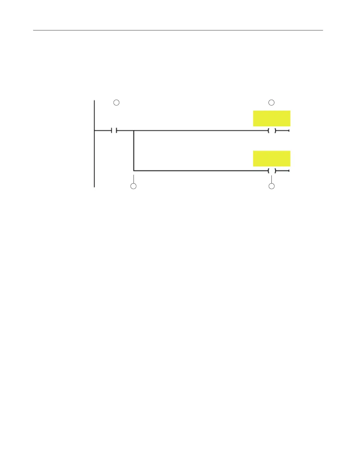
2. Insert a new network, in which you logically combine the signals:
21
3 3a
&KDQ!
$B5HVHW
'2!B
,17(51$/B
(9(17B$&.
'2!B
,17(51$/B
(9(17B$&.
No. Instruction/variable Purpose/procedure
(1) ---| |---NO contact:
"<Channel DB name>".A_Reset
The channel reset must be active, i.e. the in‐
terface signal in the corresponding channel
DB must be 1.
(2) ---( )--- Assignment
<PLC tag>
Example:
"drive1InternalEventAck"
Assign the logic operation result to the corre‐
sponding PLC tag, that you created for the
"Internal Event ACK" signal of the appropri‐
ate drive.
(3) Branch If you are using several safety-relevant drive
objects, for each drive object insert a branch
together with the operation (see 3a).
(3a) ---( )--- Assignment
<PLC tag>
Example:
"drive2InternalEventAck"
Assign the logic operation result to the corre‐
sponding PLC tag.
Figure 6-5 Inserting a new network
Result
The channel reset signal of the channel involved was logically combined with the safety-
relevant acknowledgment of faults in the individual drive objects.
Commissioning and configuring
6.3 Generating a safety program
Safety Integrated (with SINAMICS S120)
Commissioning Manual, 02/2020, A5E46305916B AB 239