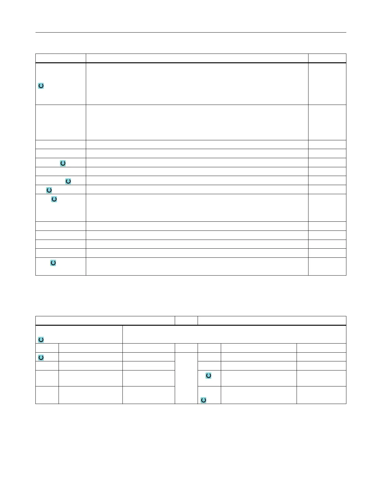
Parameter Description Unit
Machining posi‐
tion
● Single position
A polygon is milled at the programmed position (X0, Y0, Z0).
● Position pattern
Several polygons are milled at the programmed position pattern (e.g. pitch circle,
grid, line).
X0
Y0
Z0
The positions refer to the reference point:
Reference point X – (for single position only)
Reference point Y – (for single position only)
Reference point Z – (single position only and G Code position pattern)
mm
mm
mm
∅ Diameter of blank spigot mm
N Number of edges
SW or L Width across flats or edge length mm
α0 Angle of rotation Degrees
R1 or FS1 Rounding radius or chamfer width mm
Z1 Multi-edge depth (abs) or depth in relation to Z0 (inc) - (only for ∇, ∇∇∇ and ∇∇∇ edge) mm
DXY
● Maximum plane infeed
● Maximum plane infeed as a percentage of the milling cutter diameter
- (only for ∇ and ∇∇∇)
mm
%
DZ Maximum depth infeed - (only for ∇ and ∇∇∇) mm
UXY Plane finishing allowance - (only for ∇, ∇∇∇ and ∇∇∇ edge) mm
UZ Depth finishing allowance – (only for ∇ and ∇∇∇) mm
FS Chamfer width for chamfering - (for chamfering only) mm
ZFS Insertion depth of tool tip (abs or inc) - (for chamfering only) mm
%
* Unit of feedrate as programmed before the cycle call
Parameters in the "Input simple" mode
G code program parameters ShopMill program parameters
Input
● simple
Milling direction T Tool name
RP Retraction plane mm D Cutting edge number
F Feedrate * F Feedrate mm/min
mm/rev
S / V Spindle speed or constant
cutting rate
rpm
m/min
Programming technological functions (cycles)
10.2 Milling
Milling
Operating Manual, 08/2018, 6FC5398-7CP41-0BA0 447