parameterization. It is not necessary to make any indication in the order. The optical Ethernet modules are
compatible with the EN100 modules of the SIPROTEC 4 series. If the RSTP protocol or the HSR protocol is
active, the optical modules of the SIPROTEC 4 series and the SIPROTEC 5 series can be operated in a ring.
When using SIPROTEC 4 devices with module firmware ≤ V4.05 and SIPROTEC 5 devices, the maximum allow-
able number of participants is 30 devices. When using SIPROTEC 4 devices with module firmware ≥ V4.07 and
SIPROTEC 5 devices, the maximum allowable number of participants is 40 devices. When using SIPROTEC 5
devices, the maximum allowable number of participants is 40 devices.
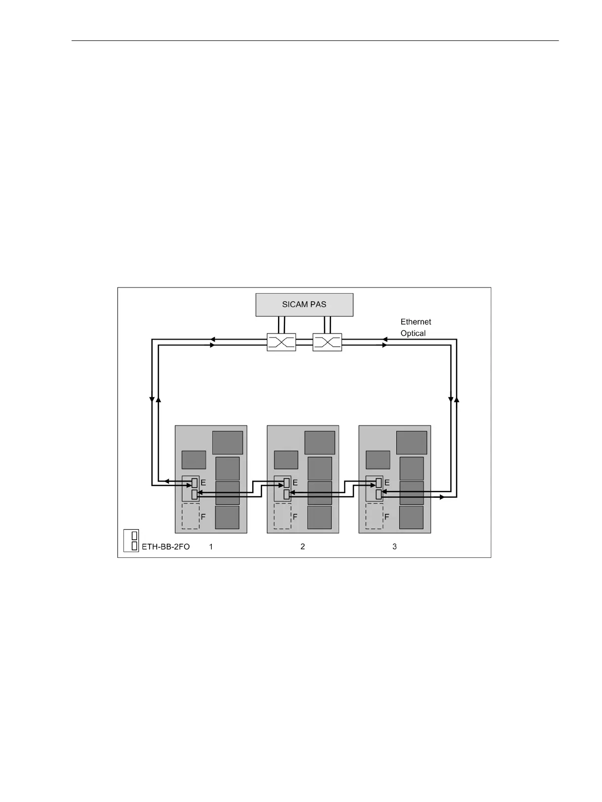
Figure 4-8 shows operation of the Ethernet modules with integrated switch function. All devices of a station
are shown which are connected to one another by means of optical fibers. The devices form optical rings. In
addition, 2 switches are used on the substation controller for the SICAM PAS. The 2 switches take the require-
ments for the redundancy into account.
Additional participants with electrical interfaces can also be connected to the SICAM PAS (for example, the
DIGSI 5 control PC). An external switch is sufficient. Optical communication modules are primarily used for this
topology, as there can be substantial distances between the devices.
If the Ethernet modules are installed in expansion modules with a CB202 PCB assembly, the power supply can
be provided with an independent battery. The integrated switch can maintain its function when the device is
switched off. The data are transmitted in optical and electric rings. This prevents opening of the ring. The ring
continues to operate when 1 or more devices are switched off.
[dweth1sw-030211-01.tif, 2, en_US]
Figure 4-8
Operation of Ethernet Modules with an Integrated Switch Function
Figure 4-9 shows the operating mode without integrated switch function. Optionally, the 2nd connection can
be connected to the 2nd switch. This connection is shown with a dashed line in Figure 4-9. The IP communica-
tion is established using the 1st connection here. If this connection fails, the system changes over to the 2nd
connection within a few milliseconds. The IP connection is retained practically without interruption using the
2nd switch. This hot-standby connection redundancy increases the availability in such configurations, as
shown in the following figure. The information on failure of the protection connection is transmitted to the
substation automation technology.
Plug-In Modules
4.2 Communication Modules
SIPROTEC 5, Hardware Description, Manual 147
C53000-G5040-C002-C, Edition 10.2017

 Loading...


