Functions
2.12 Circuit-Breaker Test
SIPROTEC, 7SD80, Manual
E50417-G1140-C474-A1, Release date 09.2011
157
The phase currents and the phase-to-ground voltages are available as measuring quantities. A flowing current
excludes that the circuit breaker is open (exception: a short-circuit between current transformer and circuit
breaker). If the circuit breaker is closed, it may, however, still occur that no current is flowing. The voltages can
only be used as a criterion for the de-energized line if the voltage transformers are installed on the feeder side.
Therefore, the device only evaluates those measuring quantities that provide information on the status of the
line according to address 1134.
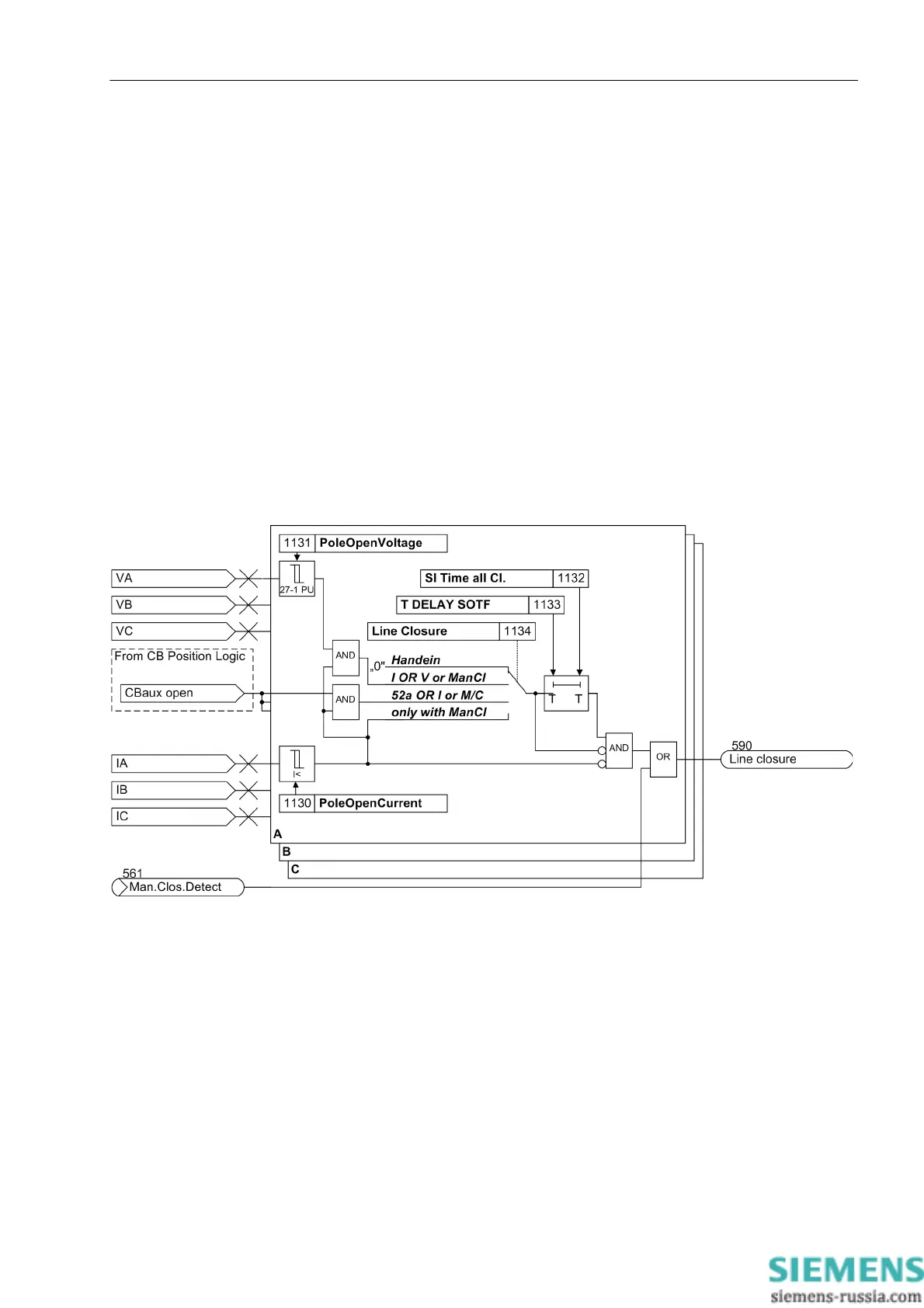
But a change-of-state, such as a voltage jump from zero to a considerable value (address 1131
PoleOpenVoltage) or the occurrence of a considerable current (address 1130 PoleOpenCurrent), can be
a reliable indicator for line energization as such changes can neither occur during normal operation nor in case
of a fault. These settings can only be changed via DIGSI at Display Additional Settings.
The position of the auxiliary contacts of the circuit breakers indicates directly the position of the circuit breaker.
The detected energization is signaled through the indication „Line closure“ (no. 590). Parameter 1132SI
Time all Cl. can be used to set the signal to a defined length. These settings can only be changed via
DIGSI at Display Additional Settings. Figure 2-61 shows the logic diagram.
In order to avoid that an energization is detected mistakenly, the state „line open“, which precedes any energi-
zation, must apply for a minimum time (settable with the address 1133 T DELAY SOTF). The default setting
for this enable delay is 250 ms. This setting can only be changed using DIGSI at Display Additional Settings.
Figure 2-61 Generation of the energization signal
The line energization detection enables the time overcurrent protection to trip instantaneously after energiza-
tion of the own line was detected.

 Loading...


