Functions
2.14 Monitoring Functions
SIPROTEC, 7SD80, Manual
E50417-G1140-C474-A1, Release date 09.2011
164
Measured-Value Acquisition – Currents
Up to four input currents are measured by the device. If the three phase currents and the ground fault current
from the current transformer neutral or a separated ground current transformer of the line to be protected are
connected to the device, their digitized sum must be zero. Faults in the current circuit are recognized if
I
F
= |I
A
+ I
B
+ I
C
+ k
I
·I
E
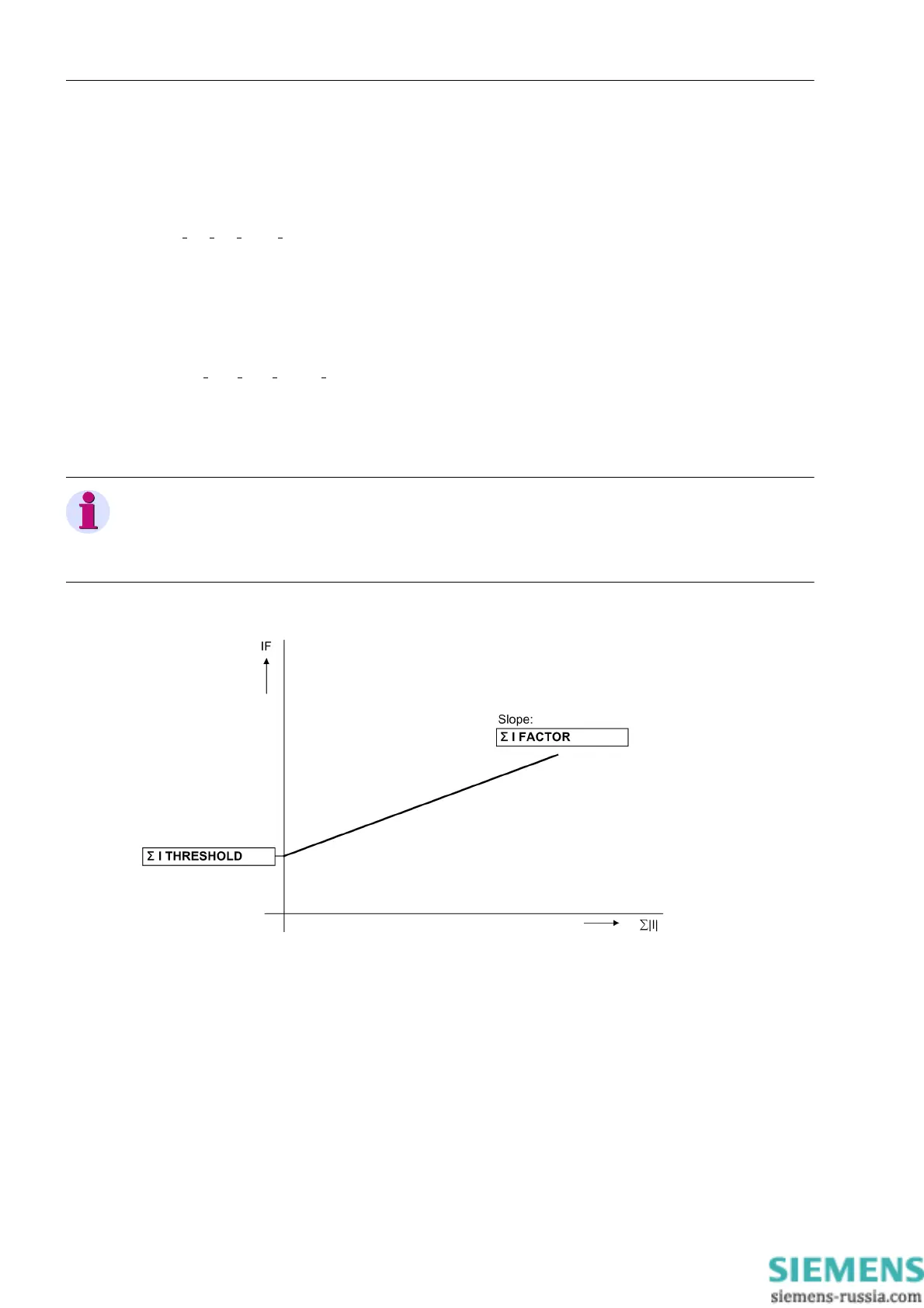
| > Σ I THRESHOLD + Σ I FACTOR·Σ | I |
Factor k
I
(address 221 I4/Iph CT) takes into account a possible different ratio of a separate I
E
transformer
(e.g. cable core balance current transformer). Σ I THRESHOLD and Σ I FACTOR are setting parameters.
The component Σ I FACTOR Σ | I | takes into account the permitted current-proportional ratio errors of the
input transducers which are particularly prevalent during large short-circuit currents (Figure 2-64). Σ | I | is the
sum of all currents:
Σ | I | = |I
A
| + |I
B
| + |I
C
| + |k
I
·I
E
|
Once a summation current fault is detected outside the context of a system disturbance, the differential protec-
tion is blocked. This fault is signaled as „Failure Σi“ (No. 289). In order to avoid a blocking due to trans-
formation errors (saturation) in case of high fault currents, this monitoring function is not effective during a
system fault.
Note
Current sum monitoring can operate properly only when the ground current of the protected line is fed to the
fourth current measuring input (I
4
) of the device. The I
4
transformer must have been configured with parameter
I4 transformer (address 220) as In prot. line.
Figure 2-64 Current sum monitoring

 Loading...


