Functions
2.14 Monitoring Functions
SIPROTEC, 7SD80, Manual
E50417-G1140-C474-A1, Release date 09.2011
166
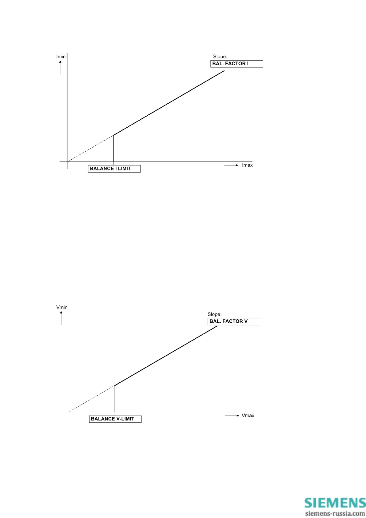
Figure 2-65 Current symmetry monitoring
Voltage Balance
During healthy system operation, a certain balance of the voltages can be assumed. The monitoring of the
measured values in the device checks this balance. The smallest phase-to-phase voltage is compared to the
largest. Imbalance is recognized if
|V
min
| / | V
max
| < BAL. FACTOR V as long as | V
max
| > BALANCE V-LIMIT
Where V
max
being the largest of the 3 phase-to-phase voltages and V
min
the smallest. The balance factor BAL.
FACTOR V (address 2903) represents the permitted imbalance of the conductor voltages while the limit value
BALANCE V-LIMIT (address 2902) is the lower limit of the operating range of this monitoring (see Figure 2-
66). The dropout ratio is about 97%.
After a settable time, this disturbance is signaled with „Fail V balance“ (no. 167).
Figure 2-66 Voltage symmetry monitoring

 Loading...


