Functions
2.14 Monitoring Functions
SIPROTEC, 7SD80, Manual
E50417-G1140-C474-A1, Release date 09.2011
170
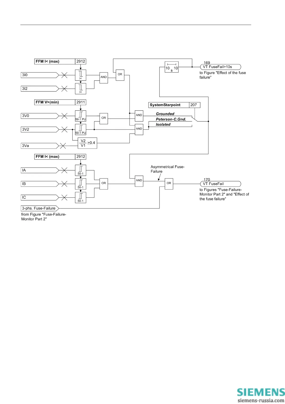
Figure 2-69 and 2-70 show the logic of the „fuse-failure monitor“.
Figure 2-69 Fuse Failure Monitor part 1: detection of the asymmetrical measuring voltage failure
Unbalanced measuring voltage failure is characterized by voltage unbalance with simultaneous current bal-
ance. If there is substantial voltage unbalance of the measured values, without current unbalance being regis-
tered at the same time, this is suggestive of an unbalanced fault in the voltage transformer secondary circuit.
Voltage unbalance is detected by the fact that either the zero sequence voltage or the negative sequence
voltage exceed a settable value FFM V>(min) (address 2911). The current is assumed to be sufficiently bal-
anced if both the zero sequence as well as the negative sequence current are below the settable threshold FFM
I< (max) (address 2912).
In ungrounded systems (address 207 SystemStarpoint), the zero sequence voltage is no reliable criterion
since a considerable zero sequence voltage occurs also in case of a simple ground fault where a significant
zero sequence current does not necessarily flow. Therefore, the zero sequence voltage is not evaluated in such
systems but only the negative sequence voltage and the ratio of negative sequence voltage to positive se-
quence voltage.
As soon as this state is recognized, all functions that operate on the basis of undervoltage are blocked. The
immediate blocking requires that current flows in at least one of the phases. The differential protection can be
switched to emergency mode if the overcurrent protection is parameterized accordingly (see also Section 2.4).
The indication „VT FuseFail“ (no. 170) signals the immediate effect of the „fuse failure monitor“. To detect
unbalanced measuring voltage failure, at least one phase current must exceed the value FFM I< (max) (ad-
dress 2912).

 Loading...


