Functions
2.14 Monitoring Functions
SIPROTEC, 7SD80, Manual
E50417-G1140-C474-A1, Release date 09.2011
181
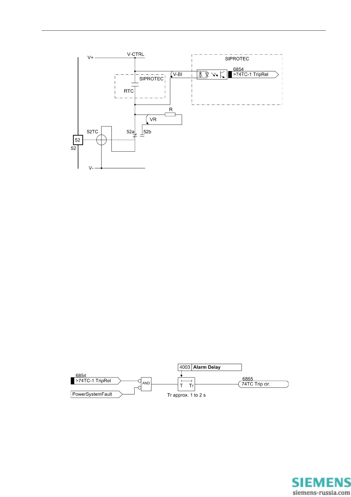
Figure 2-75 Principle of the trip circuit monitoring with one binary input
RTC Relay trip contact
52 Circuit breaker
52TC Circuit-breaker trip coil
52a Circuit-breaker auxiliary contact (NO contact)
52b Circuit-breaker auxiliary contact (NC contact)
V-CTRL Control Voltage for trip circuit
V-BI Input voltage for binary input
R Bypass resistor
VR Voltage at bypass resistor
During normal operation, the binary input is activated (logical condition „H“) when the trip contact is open and
the trip circuit is intact, because the monitoring circuit is closed by either the circuit-breaker auxiliary contact (if
the circuit breaker is closed) or through the bypass resistor R. Only as long as the trip contact is closed, the
binary input is faulted and thereby deactivated (logical condition „L“).
If the binary input is permanently deactivated during operation, an interruption in the trip circuit or a failure of
the (trip) control voltage can be assumed.
The trip circuit monitor does not operate during system faults. A momentary closed tripping contact does not
lead to a failure message. If however other trip relay contacts from different devices are connected in parallel
in the trip circuit, the failure alarm must be delayed by Alarm Delay (refer also to Figure 2-76). After the fault
in the trip circuit is removed, the alarm is reset automatically after the same time.
Figure 2-76 Logic diagram for trip circuit monitoring with one binary input

 Loading...


