Mounting and Commissioning
3.1 Mounting and Connections
SIPROTEC, 7SD80, Manual
E50417-G1140-C474-A1, Release date 09.2011
234
Trip Circuit Supervision
It must be noted that two binary inputs or one binary input and one bypass resistor R must be connected in
series. The pick-up threshold of the binary inputs must therefore be substantially below half
the rated control
DC voltage.
If two binary inputs are used for the trip circuit supervision, these binary inputs must be isolated, i.o.w. not be
communed with each other or with another binary input.
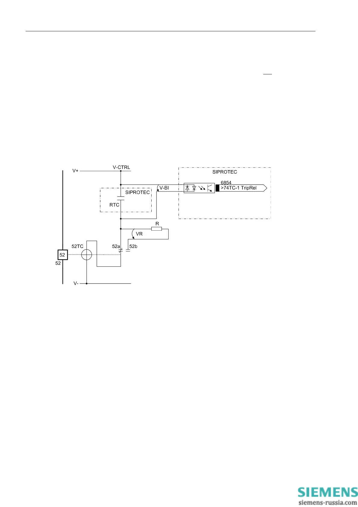
If one binary input is used, a bypass resistor R must be used (refer to
Figure 3-2
). This resistor R is connected in
series with the second circuit breaker auxiliary contact (Aux2), to also allow the detection of a trip circuit failure
when the circuit breaker auxiliary contact 1 (Aux1) is open, and the command relay contact has reset. The value
of this resistor must be such that in the circuit breaker open condition (therefore Aux1 is open and Aux2 is
closed) the circuit breaker trip coil (TC) is no longer picked up and binary input (BI1) is still picked up if the
command relay contact is open.
Figure 3-2 Principle of the trip circuit monitoring with one binary input
RTC Relay trip contact
52 Circuit breaker
52TC Circuit-breaker trip coil
52a Circuit-breaker auxiliary contact (NO contact)
52b Circuit-breaker auxiliary contact (NC contact)
V-CTRL Control Voltage for trip circuit
V-BI Input voltage for binary input
R Bypass resistor
VR Voltage at bypass resistor

 Loading...


