Mounting and Commissioning
3.2 Checking Connections
SIPROTEC, 7SD80, Manual
E50417-G1140-C474-A1, Release date 09.2011
254
Connections at port B
Table 3-3 Assignments of the port B sockets
1)
Pin 7 also carries the RTS signal with RS232 level when operated as RS485 interface. Pin 7 must therefore
not be connected!
2)
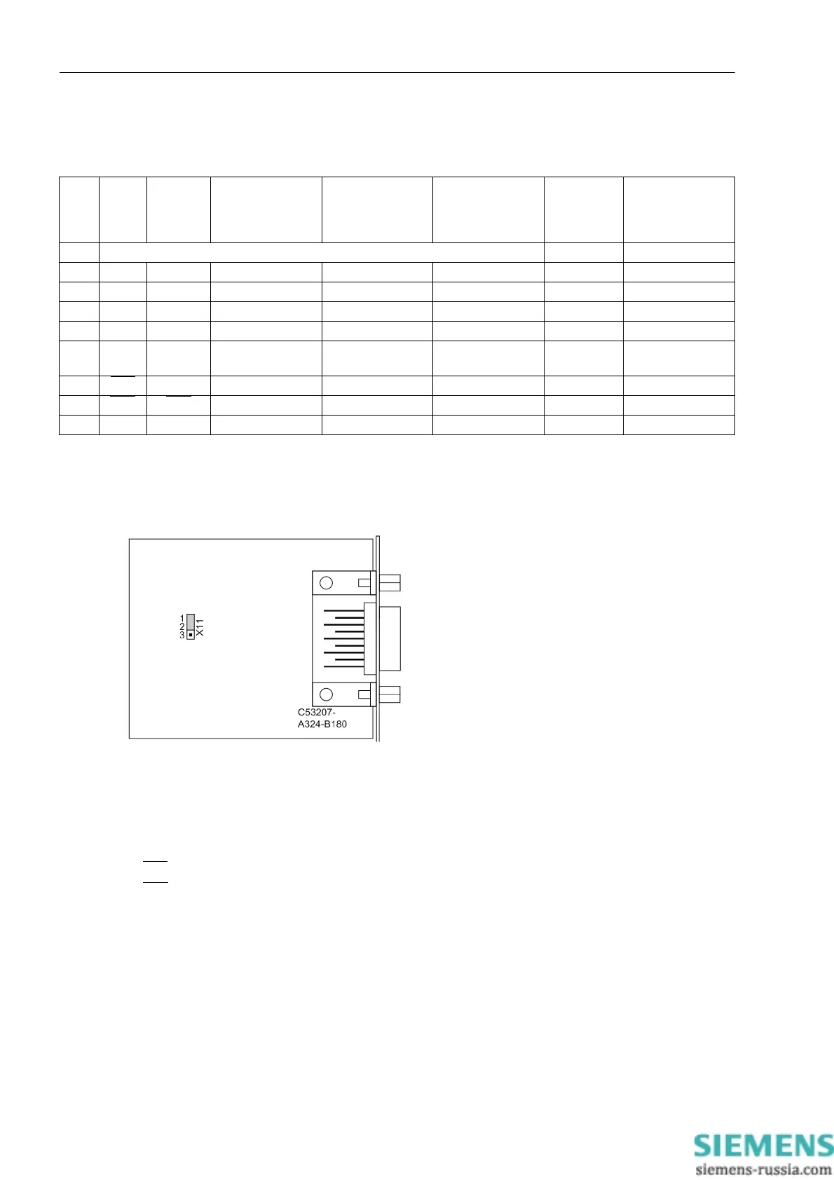
For time synchronization via RS232, the X11 jumper must be in position 1-2.
Figure 3-19 Position of jumper X11 on the RS 232 interface
With data cables, the connections are designated according to DIN 66020 and ISO 2110:
• TxD = Data output
• RxD = Data input
•RTS
= Request to send
•CTS
= Clear to send
• GND = Signal/Chassis Ground
The cable shield is to be grounded at both ends. For extremely EMC-prone environments, the GND may be
connected via a separate individually shielded wire pair to improve immunity to interference.
Pin
No.
RS232 RS232
time syn-
chroniza-
tion
2)
RS485 Profibus DP,
RS485
Modbus RS485
DNP3.0 RS485
Ethernet
EN 100
IEC 60870–5–103
redundant
1 Shield (with shield ends electrically connected) Tx+ B/B’ (RxD/TxD-P)
2 RxD – – – – Tx– A/A’ (RxD/TxD-N)
3 TxD – A/A’ (RxD/TxD-N) B/B’ (RxD/TxD-P) A Rx+ –
4 – – – CNTR-A (TTL) RTS (TTL level) — –
5 GND GND C/C’ (GND) C/C’ (GND) GND1 — –
6 – – – +5 V (max. load <
100 mA)
VCC1 Rx– –
7RTS
––
1)
––—–
8CTS
CTS B/B’ (RxD/TxD-P) A/A’ (RxD/TxD-N) B — –
9 – – – – – not available not available

 Loading...


