Mounting and Commissioning
3.3 Commissioning
SIPROTEC, 7SD80, Manual
E50417-G1140-C474-A1, Release date 09.2011
269
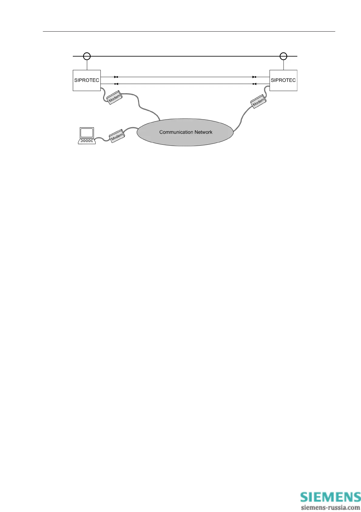
Figure 3-29 Connection of the PC via modem - basic example
Checking a Connection Using Direct Link
In case of an optical fiber link (as shown in Figure 3-27 or 3-29) or via copper conductor link, this connection is
checked as follows:
• Both devices at the link ends have to be switched on.
• Check in the event log or in the spontaneous annunciations:
– If the message „PDI FO con. to.“ (protection data interface connected with no. 3243) is provided
with the device index of the other device in case of an optical fiber conductor, a link has been established
and one device has recognized the other.
– If the message „PDI Cu con. to.“ (protection data interface connected with no. 3244) is provided
with the device index of the other device in case of a copper connection, a link has been established and
one device has recognized the other.
– The device indicates „Slave Login“, no. 3492 or „Master Login“, no. 3491 if the other device has
been detected.
• In case of an incorrect communication link, the indication „PDI FO faulty“ (no. 3230) or „PDI Cu
faulty“ (no. 3232) is displayed. In this case, check the connection again:
– Are the connections correct and not swapped?
– Are the cables free from mechanical damage, intact and the connectors locked?
– Otherwise repeat the verification.
Continue with the margin heading „Consistency of Connection and Parameterization“.
Consistency of Connection and Parameterization
Having performed the above checks, the linking of a device pair has been completely tested and connected to
auxiliary supply voltage. Now the devices contact each other on their own account.
• Check now the Event Log or in the spontaneous annunciations of the device where you are working:
– Indication no. 3243 „PDI FO con. to.“ (protection interface connected with).
– If the parameterization of the devices is consistent, i.e. the requirements have been observed when
setting the function scope (Section 2.1.1), the power system data 1 (2.1.3.1), the power system data 2
(2.1.6.1), the protection interface parameters (Section 2.1.8.2), the fault indication for the verified inter-
face also disappears, i.e. no. 3230 „PDI FO faulty“ or no. 3232 „PDI Cu faulty“. The commu-
nication and consistency check has thus been completed.

 Loading...


