Configuration
68
7SS52 V4 Manual
C53000-G1176-C182-3
CT location The DIGSI Plant Configuration evaluates the CT location for the end fault protection
and for stations with transfer busbars. The settings mean in this context:
• busside towards busbar means that the transformer is located between the circuit
breaker and the busbar isolator (Figure 4-15, page 64, 1a)
• busside towards line means that the transformer is located upstream of the feeder
isolator, i.e. between the circuit breaker and the feeder isolator (refer to Figure 4-
15, page 64, 1b)
• line side means that the transformer is located downstream of the feeder isolator
(Figure 4-15, page 64, 2).
For the end fault protection, the position of the current transformer relative to the circuit
breaker is important (position 1 a or 1b and 2 respectively). For the behaviour or the
protection in bypass operation, the position of the current transformer relative to the
transfer busbar isolator is important (position 1a and 1b respectively or 2).
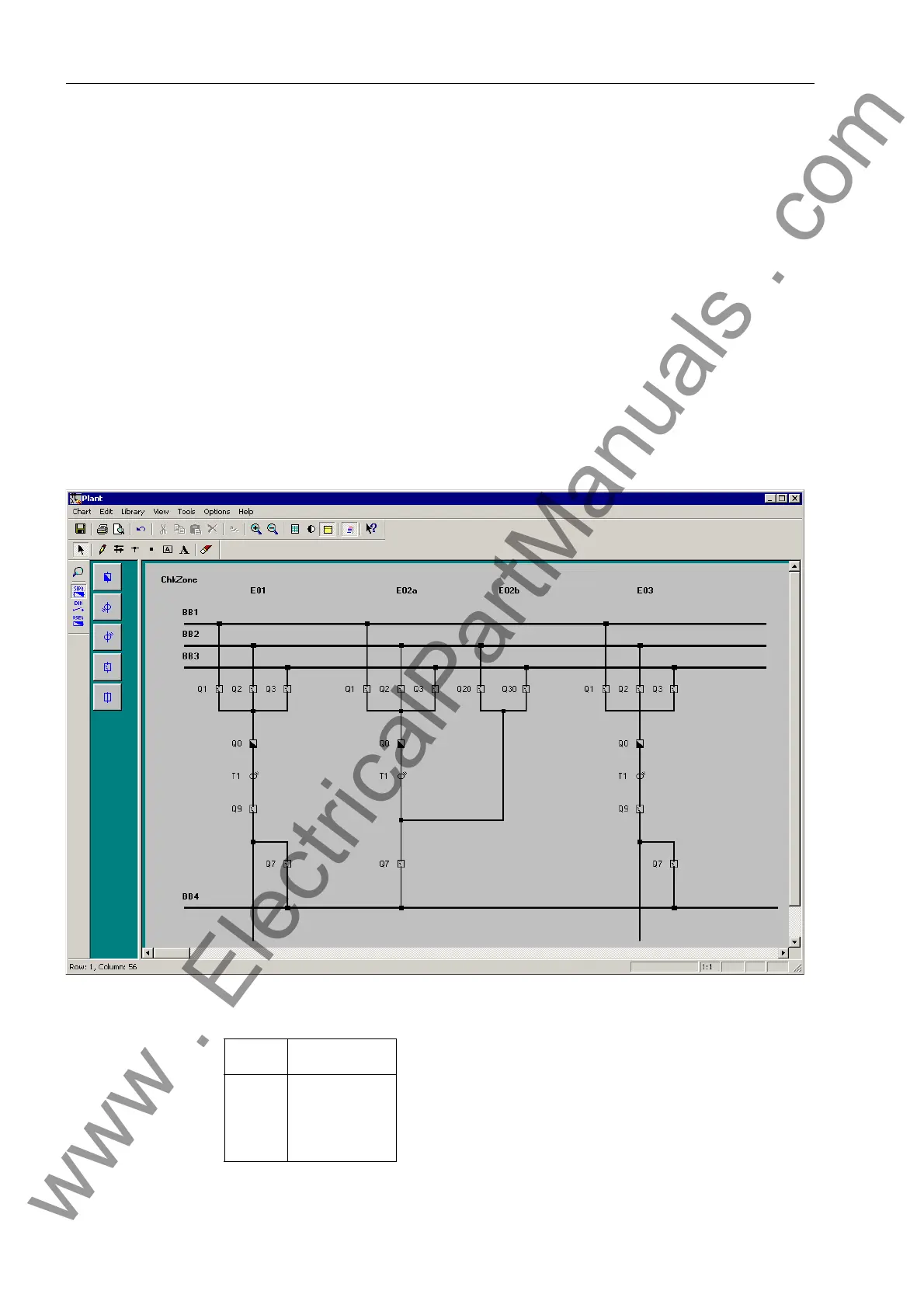
In “2-bay couplers”, CT is only assigned to one bay unit (Figure 4-17, page 68 and Fig-
ure 4-18, page 69).
Figure 4-17 Example for the configuration of a 2-bay coupler with one CT
Bay Bay unit
E01
E02a
E02b
E03
BU 1
BU 2
BU 3
BU 4
www . ElectricalPartManuals . com

 Loading...


