Diagnostics
5.2 Diagnostics using LEDs
Commissioning with Startdrive
Commissioning Manual, 11/2017, 6SL3097-4AA10-0BP1
319
Control Interface Module in the Motor Module chassis format
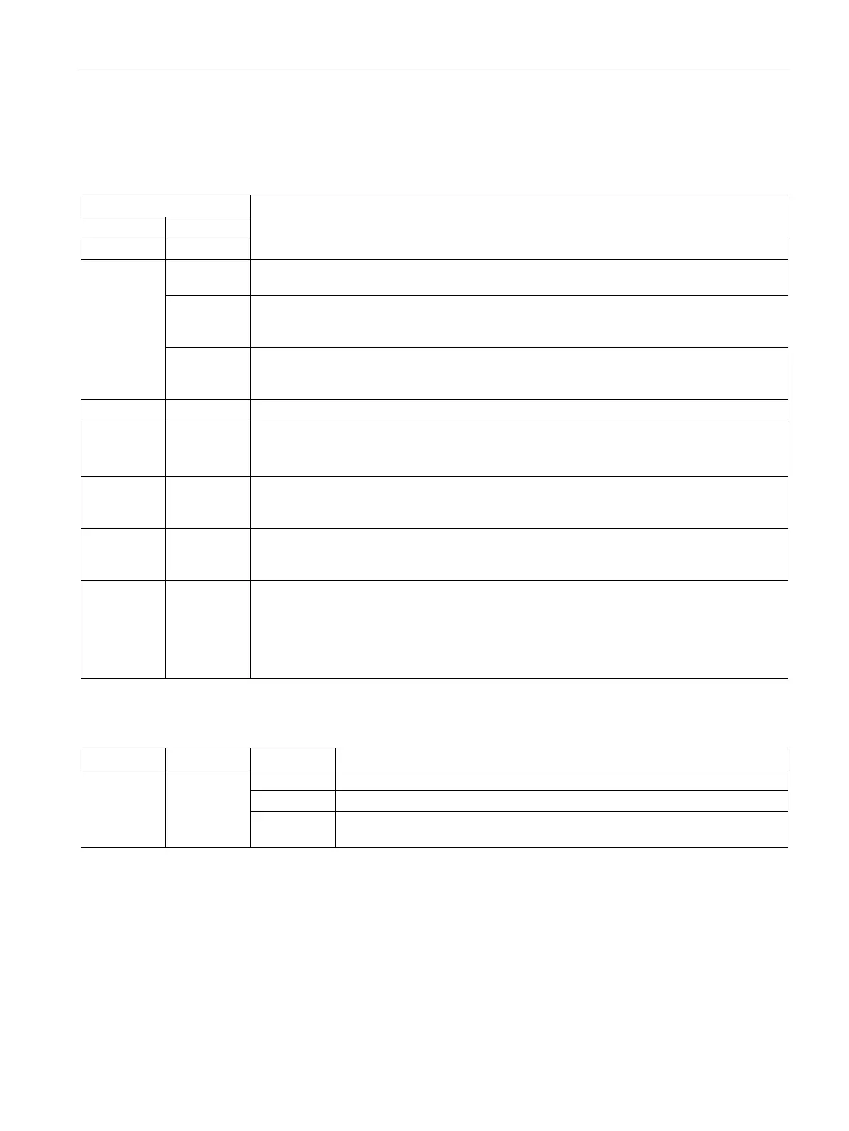
Table 5- 16 Meaning of the LEDs "Ready" and "DC Link" on the Control Interface Module in the Motor Module
Off Off The electronic power supply is missing or lies outside the permissible tolerance range.
Green Off The component is ready for operation and cyclic DRIVE-CLiQ communication is taking
Orange The component is ready for operation and cyclic DRIVE-CLiQ communication is taking
place.
The DC link voltage is present.
Red The component is ready for operation and cyclic DRIVE-CLiQ communication is taking
place.
The DC link voltage is too high.
DRIVE-CLiQ communication is being established.
Red --- At least one fault is present in this component.
Note:
LED is activated irrespective of any reconfiguring of the corresponding messages.
Green / red
flashing light
--- Firmware is being downloaded.
Green / red
flashing light
--- Firmware download is complete. Wait for POWER ON.
Green /
orange
or
red / orange
flashing light
--- Component detection using LED is activated (p0124).
:
Both options depend on the LED status when module recognition is activated via p0124 = 1.
Table 5- 17 Meaning of the LED "POWER OK" on the Control Interface Module in the Motor Module
POWER OK Green
DC link voltage < 100 V and voltage at -X9:1/2 less than 12 V.
The component is ready for operation.
Flashing
There is a fault. If the LED continues to flash after you have performed a
POWER ON, please contact your Siemens service center.
 Loading...


