EN 92 A6V10816676_----_d Siemens Building Technologies
Integration
To integrate the meter, proceed as follows:
• Determine the installation location according to the marking on the meter.
• Consider the meter's dimensions and check whether there is enough space.
• Beoreinstallingthemeterushthesstemthoroughlandclosetheball
valves.
• ismantletheushingtuberomtheinstallation
• Remove the threaded protective caps on the new meter.
• Mount the meter vertically or horizontally between two ball valves in such a
way that the arrow on the ometeringelement corresponds to the direction
ooPleasereertotheinstallationsituationsandtheolloingeamples
• Install the temperature sensor in the same circuit as the meter.
Important installation notes
The sensor cables (e.g. temperature sensor cable) must be routed at a
distance of at least 50 mm to sources of electromagnetic interference
sitcheselectricmotorsuorescentlamps
An installed meter is a pressurized component. Risk of scolds from hot
water. Fitting only by trained experts.
Refer to operating instructions, operating conditions and installation
requirements in accordance with EN 1434-6.
Heedcorrectsupploorreturnoinstallationandtheinstallation
position of the ometeringelement.
Always use new seals when installing a new meter.
Temperature sensors can be installed in ball valves, in T-pieces, directly
immersed or in immersion sleeves. The ends of the sensors must reach
at least to the centre of the pipe cross-section.
Notenationalandcountrspecicregulationsconcerningtheuseo
immersion sleeves.
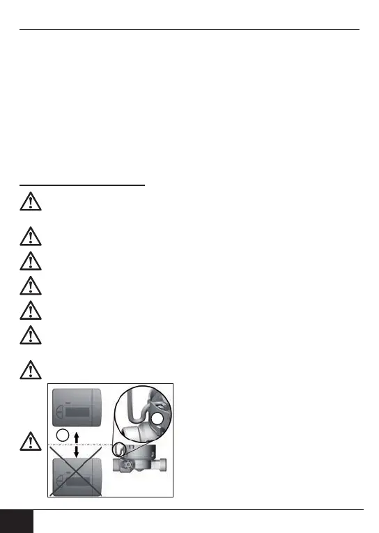
If there is a condensation risk or for refrig-
eration applications, the calculator unit
must be installed on a wall and higher
thantheometeringelement
For wall-mounted installation the cable
from the calculator unit must be routed in
suchaathatcondensationcannoto
ordripintothecoilbodotheo
metering element.
1
2
 Loading...