SECTION 2
ALARM CONDITIONS
INTRODUCTION
CAUTION
FOLLOW LOCAL OPERATING PROCEDURES WHEN INVESTIGATING ALARM CONDITIONS.
NOTE:
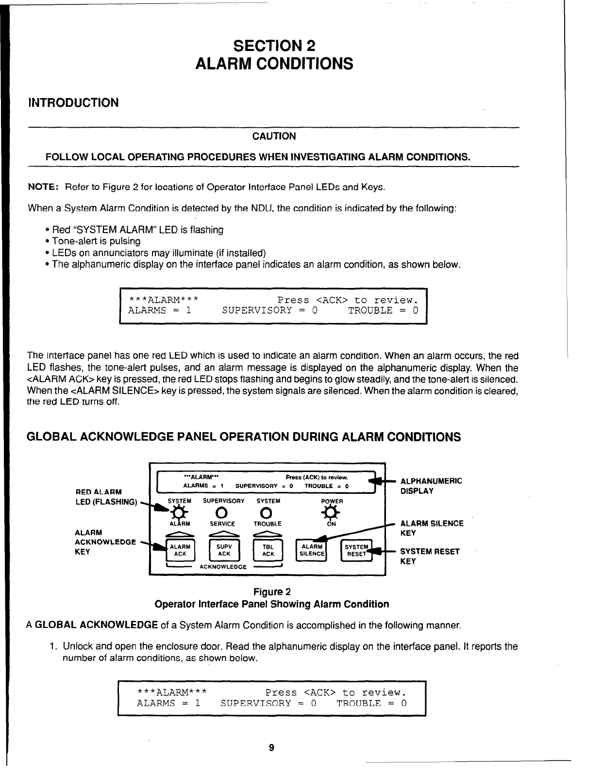
Refer to Figure 2 for locations of Operator Interface Panel LEDs and Keys.
When a System Alarm Condition is detected by the NDU, the condition is indicated by the following:
l
Red “SYSTEM ALARM” LED is flashing
l
Tone-alert is pulsing
l
LEDs on annunciators may illuminate (if installed)
l
The alphanumeric display on the interface panel indicates an alarm condition, as shown below.
I
***ALARM***
Press <ACK> to review.
ALARMS = 1
SUPERVISORY = 0
TROUBLE = 0
I
The interface panel has one red LED which is used to indicate an alarm condition. When an alarm occurs, the red
LED flashes, the tone-alert pulses, and an alarm message is displayed on the alphanumeric display. When the
<ALARM ACK> key is pressed, the red LED stops flashing and begins to glow steadily, and the tone-alert is silenced.
When the <ALARM SILENCE> key is pressed, the system signals are silenced. When the alarm condition is cleared,
the red LED turns off.
GLOBAL ACKNOWLEDGE PANEL OPERATION DURING ALARM CONDITIONS
RED ALARM
LED (FLASHING)
ALARM
ACKNOWLEDGE
KEY
“‘ALARY”
Press (ACK) to review.
ALARMS = 1
SUPERVISORY = 0
TROUBLE = 0
SUPERVISORY
SYSTEM POWER
ACKNOWLEDGE -
- ALPHANUMERIC
DISPLAY
c ALARM SlLENCE
KEY
- SYSTEM RESET
KEY
Figure 2
Operator Interface Panel Showing Alarm Condition
A
GLOBAL ACKNOWLEDGE
of a System Alarm Condition is accomplished in the following manner.
1. Unlock and open the enclosure door. Read the alphanumeric display on the interface panel. It reports the
number of alarm conditions, as shown below.
1
***ALA~“**
Press <ACK> to review.
ALARMS = 1
SUPERVISORY = 0 TROUBLE = 0
9