TELEPHONE OPERATION
PHONE LED/SWITCH MODULE
The phone switches are also three-position, momentary switches. The up position is ON, down is OFF, and the
center position is the normal position for all phone switches. The phone switches are Phone Piezo Silence and
Phone Circuit Select switches. The Phone Silence/Active switch is used to silence the NDU panel tone-alert signal
without connecting the remote phone. When this switch is in the UP position, its LED will turn ON. Phone Circuit
Select Switches are used individually to connect remote phone circuits to the master phone talk line. Each LED
tracks the active state of its circuit. When the phone circuit is active, the LED will turn ON. It will turn OFF when
deactivated.
HOW TO OPERATE THE TELEPHONE
(SEE FIGURE 25)
Operate the phone system in the following manner.
1. When a remote phone is plugged in or a remote handset is lifted, the red Phone Circuit LED flashes to show
the incoming call. Both the remote handset ring signal and the panel’s tone-alert will sound.
2. Pick up the Master Phone.
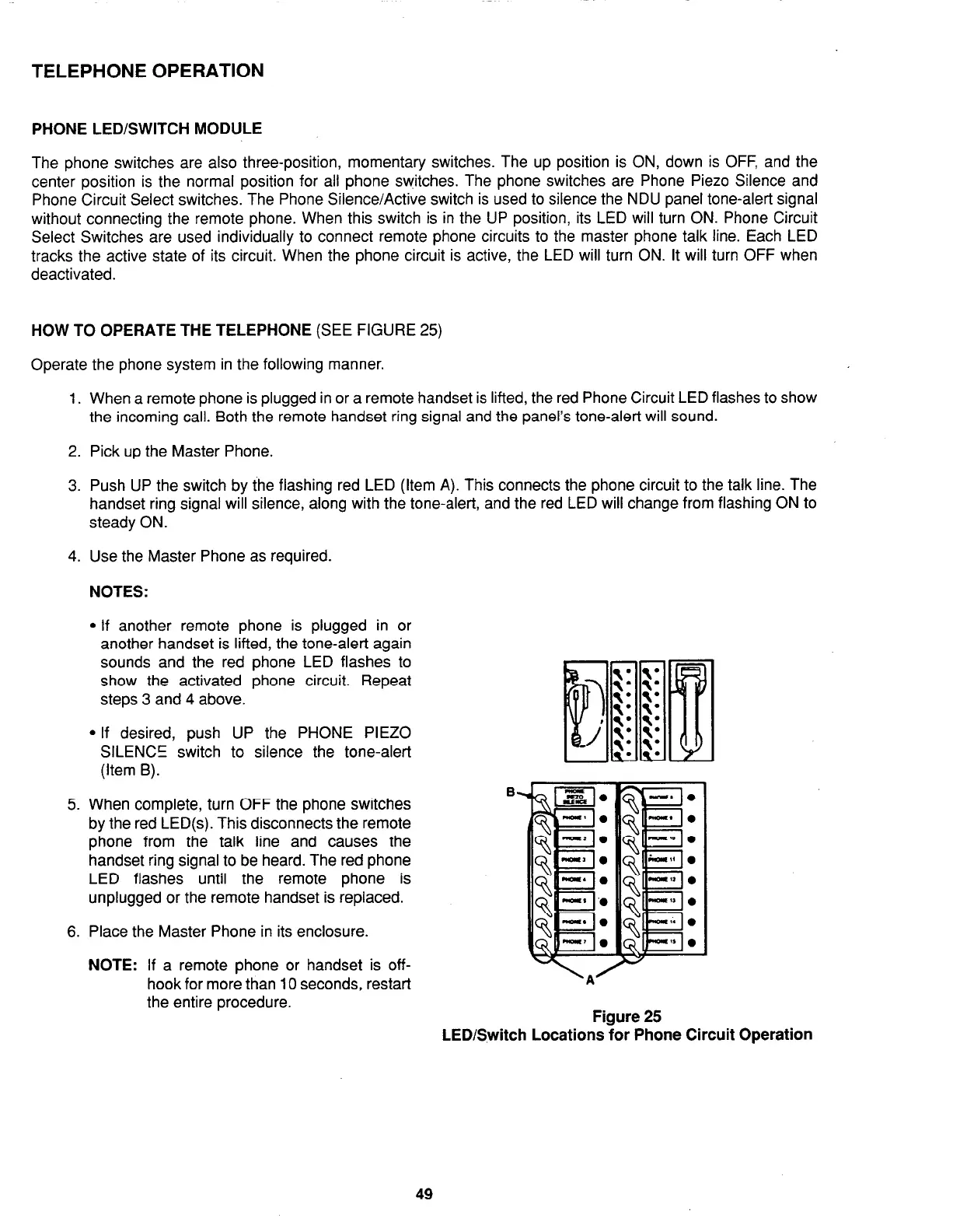
3. Push UP the switch by the flashing red LED (Item A). This connects the phone circuit to the talk line. The
handset ring signal will silence, along with the tone-alert, and the red LED will change from flashing ON to
steady ON.
4. Use the Master Phone as required.
NOTES:
l
If another remote phone is plugged in or
another handset is lifted, the tone-alert again
sounds and the red phone LED flashes to
show the activated phone circuit. Repeat
steps 3 and 4 above.
l
If desired, push UP the PHONE PIEZO
SILENCE switch to silence the tone-alert
(Item B).
5. When complete, turn OFF the phone switches
by the red LED(s). This disconnects the remote
phone from the talk line and causes the
handset ring signal to be heard. The red phone
LED flashes until the remote phone is
unplugged or the remote handset is replaced.
6. Place the Master Phone in its enclosure.
NOTE:
If a remote phone or handset is off-
hook for more than 10 seconds, restart
the entire procedure.
Figure 25
LED/Switch Locations for Phone Circuit Operation
49