NOTE:
Any system point may be viewed on the alphanumeric display using the above procedure. Press
the required Prefix keys; then, use the Programmer’s Report to identify the required point: address.
Enter the required point address. Press the <FUNCTION> key to display information about the
point you entered.
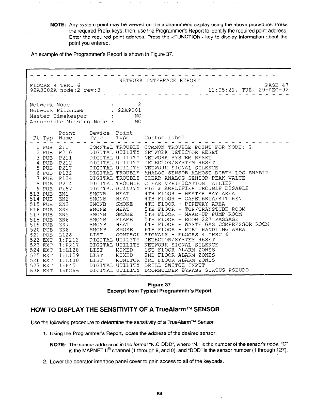
An example of the Programmer’s Report is shown in Figure 37.
_--_-----------------~--~~-~---~-------
NETWORK INTERFACE REPORT
FLOORS 4 THRU 6
:?AGE 47
92A3002A node:2 rev:3
11:05:21, TUti, 29-DEC-92
______--------- --
-_-----__--------s-m--
Network Node
2
Network Filename
: 92199001
Master Timekeeper
NO
Annunciate Missing Node : NO
Pt TYP
- - - -
1 PUB
2 PUB
3 PUB
4 PUB
5 PUB
6 PUB
7 PUB
8 PUB
9 PUB
513 PUB
514 PUB
515 PUB
516 PUB
517 PUB
518 PUB
519 PUB
520 PUB
521 PUB
522 EXT
523 EXT
524 EXT
525 EXT
526 EXT
527 EXT
528 EXT
Point
Name
-2
.:I - -
P210
P211
P212
P217
P132
P134
P214
P187
ZNl
ZN2
ZN3
ZN4
ZN5
ZN6
ZN7
ZN8
L128
l:P212
l:P217
l:L128
l:L129
l:L130
l:P45
l:P256
Device
Point
Type
Type
- - - - - - - - -
COMNTBL TROUBLE
DIGITAL UTILITY
DIGITAL UTILITY
DIGITAL UTILITY
DIGITAL UTILITY
DIGITAL TROUBLE
DIGITAL TROUBLE
DIGITAL TROUBLE
DIGITAL UTILITY
SMONB
HEAT
SMONB
HEAT
SMONB
SMOKE
SMONB
HEAT
SMC'NB
SMOKE
SMONB
FLAME
SMONB
HEAT
SMONB
SMOKE
LIST
CONTROL
DIGITAL UTILITY
DIGITAL UTILITY
LIST
MIXED
LIST
MIXED
LIST
MONITOR
DIGITAL UTILITY
DIGITAL UTILITY
Custom Label
_____--__-__--_-------
COMMON TROUBLE POINT FOR NODE: 2
NETWORK DETECTOR RESET
NETWORK SYSTEM RESET
DETECTOR/SYSTEM RESET
NETWORK SIGNAL SILENCE
ANALOG SENSOR ALMOST DIRTY LOG ENABLE,
CLEAR ANALOG SENSOR PEAK VALUE
CLEAR VERIFICATION TALLIES
VIG & AMPLIFIER TROUBLE DISABLE
4TH FLOOR -
HEATER BAY AREA
4TH FLOOR - CAFETERIA/KITCHEN
4TH FLOOR - PIPEWAY AREA
5TH FLOOR - TOP/TRANSTUBE ROOM
5TH FLOOR - MAKE-UP PUMP ROOM
5TH FLOOR - ROOM 227 PASSAGE
6TH FLOOR - WASTE GAS COMPRESSOR R00M
6TH FLOOR - FUEL HANDLING AREA
SIGNALS - FLOORS 4 THRLJ 6
DETECTOR/SYSTEM RESET
NETWORK SIGNAL SILENCE
1ST FLOOR ALARM ZONES
2ND FLOOR ALARM ZONES
3RD FLOOR ALARM ZONES
DRILL SWITCH INPUT
DOORHOLDER BYPASS STATUS PSEUDO
Figure 37
Excerpt from Typical Programmer’s Report
HOW TO DISPLAY THE SENSITIVITY OF A TrueAlarmTM SENSOR
Use the following procedure to determine the sensitivity of a TrueAlarmTM Sensor.
1. Using the Programmer’s Report, locate the address of the desired sensor.
NOTE:
The sensor address is in the format “N:C-DDD”, where “N:” is the number of the sensor’s node, “C”
is the MAPNET II@ channel (1 through 9, and 0), and “DDD” is the sensor number (1 through 127).
2. Lower the operator interface panel cover to gain access to all of the keypads.
64