51
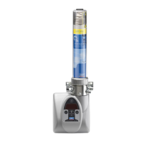
6.8.5 Initial filling of an empty pump with
double-lip follower plate
Fig.
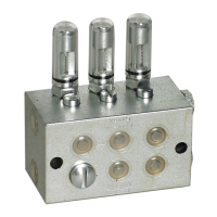
Initial filling of an empty pump with double-lip follower
plate
NOTE
For initial filling of a pump delivered without
lubricant, the pump is fitted with a bleed thread
(Fig.
33/1) and a “Read instructions” sticker
33/2). The bleed thread ensures that the air
under the follower plate can escape when filling the
pump for the first time. This prevents faults due to
negative effects on the suction characteristics of the
pump resulting from air inclusions under the followe
r
plate. The bleed thread (Fig.
33/1) is ONLY required
for the initial filling and must then be removed
together with the “Read instructions” sticker
(Fig.
33/2).
When filling for the first time, proceed as described
below:
1. Align the pump so that it is upright.
2. Connect the filling pump to the filler nipple (Fig. 33/5).
3. Switch on the filling pump and carefully fill the space
(Fig. 33/4) under the follower plate (Fig. 33/3)
completely with lubricant, while observing the follower
plate.
4. Switch off the filling pump once all the air under the
follower plate has been displaced.
5. Detach the sticker (Fig. 33/2) and slowly and carefully
pull the bleed thread (Fig. 33/1) down and out of the
pump.
6. Switch on the filling pump and fill the reservoir with
lubricant up to just below the - MAX - marking.
7. Properly dispose of the bleed thread and the sticker.
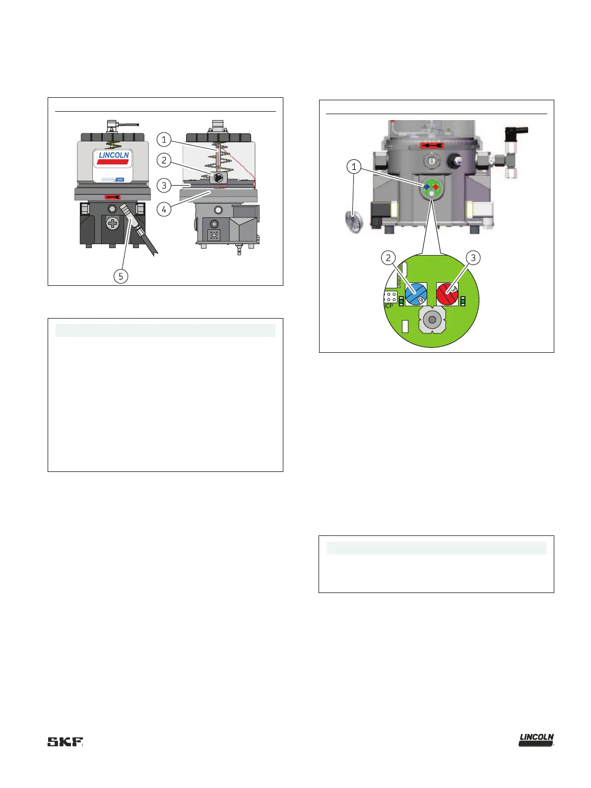
6.9 Setting the lubrication time and
pause time
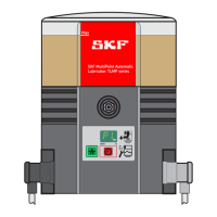
Fig.
P203 with control circuit board V10-V23
The lubrication and pause times are set using the two
rotary switches on the control circuit board. See Table 28
for the times that correspond to the switch positions.
Proceed as follows for setting:
1. Remove the screw cap (Fig. 34/1) together with the
packing ring
2. Set the pause time by turning the left-hand, blue rotary
switch (Fig. 34/ 2)
3. Set the lubrication time by turning the right-hand, red
rotary switch (Fig. 34/3)
4. Reinstall the screw cap together with the packing ring
– Tightening torque 2 Nm ±0.2 Nm [1.48 ft.lb.
±0.15 ft.lb.]
NOTE
The newly set lubrication and pause times do not take
effect until you switch the power supply to the pump
off and back on again.