74
Connection diagram of the signal line on the reservoir cover
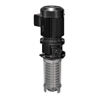
15.1.2 Recommended contact protection for switching inductive loads
Fig.
Contact protection
1 Contact of the low-level signal
2 Interference suppression diode (free-wheeling diode)
When switching inductive loads with direct voltage, the operator should provide the contact protection measure shown in
Figure 42 to protect the contacts of the low-level signal.
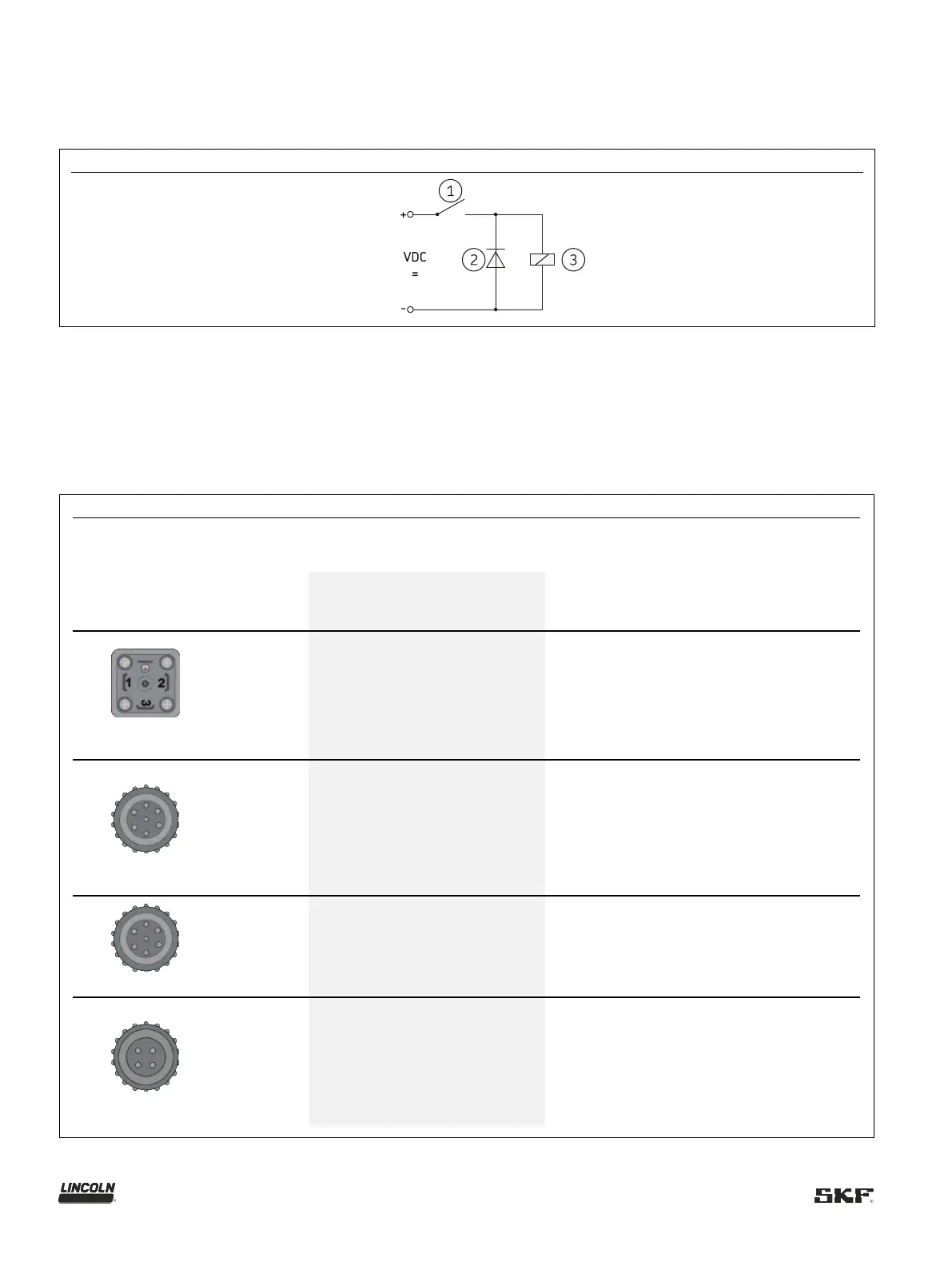
15.1.3 Overview of cables and possible connections
Table
Cables and possible connections
section
rating
4xAWG 18
IP 67
connector
664-34428-3 10 m 7×1.5 mm² IP 69K
664-34167-2 10 m
3x1.5 mm²
2x0.5 mm²
(WH, YE)
IP 69K
664-34167-9 10 m 4×0.5 mm²
IP 69K
N
N