43
6.3.2 Assembly holes
NOTICE
Damage to the main machine and the pump
The assembly holes should be created only on non-
load
-bearing parts of the main machine. Do not
two parts which move in opposite
directions to one another (e.g., machine base and
machine assembly).
When installing pumps with reservoirs of 11 l
gal.] or greater, the flatness of the upper and
lower installation surfaces must not vary by more
than 1 mm [0.039 in.] from one another.
The pump housing is fastened at the assembly holes
using:
• 2 or 3 screws M8 (8.8)
• 2 or 3 hexagon nuts M8 (8.8)
• 2 or 3 washers (8)
Diameter of the holes:
∅ 9 mm [0.35 in.]
Pumps with 2 l [0.53 gal] reservoir:
The pumps are fastened at the two lower fastening points
(Fig. 20/1) or (Fig. 20/2) of the pump housing:
A1 = 162 mm [6.38 in.]
B1 = 180 mm [7.09 in.]
A2 = 124 mm [4.88 in.]
B2 = 112 mm [4.41 in.]
Pumps with 2 l flat reservoir [0.53 gal] or 4 l [1.06 gal],
8 l [2.11 gal], 11 l [2.90 gal], or 15 l [3.96 gal] reservoir:
The pumps are fastened at the three lower fastening
points (Fig. 20/1) or (Fig. 20/2) and (Fig. 20/3) of the
pump housing:
C1 = 83 mm [3.27 in.]
C2 = 95 mm [3.74 in.]
Fig.
Fastening points at the bottom of the pump housing
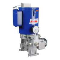
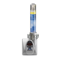
Pumps with 11 l [2.90 gal] or 15 l [3.96 gal] reservoir:
The pumps are fastened at the three lower fastening
points (Fig. 20/1) or (Fig. 20/2) and (Fig. 20/3) of the
pump housing and also at 2 upper assembly points (D):
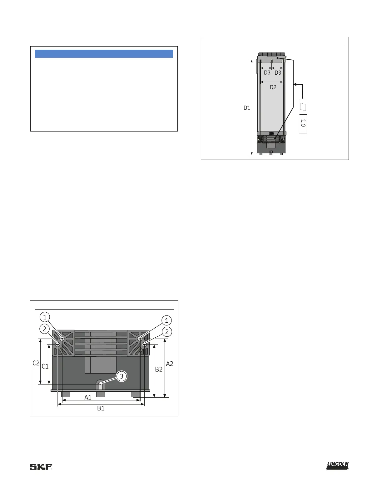
Fig.
Assembly holes at the top of pumps with 11 l and 15 l reservoirs
The mounting bracket at the top is fastened using:
• 2 screws M8 (8.8)
• 2 hexagon nuts M8 (8.8)
• 2 washers (8)
Tightening torque: 18 Nm ± 1.0 Nm
[13.27 ft.lb. ± 0.74 ft.lb.]
Diameter of the holes on the top mounting bracket:
∅ 9 mm [0.35 in.]
With 11 l [2.90 gal] reservoir:
D1 = 557 mm [21.93 in]
D2 = 160 mm [6.30 in.]
D3 = 80 mm [3.15 in.]
With 15 l [3.96 gal] reservoir:
D1 = 675 mm [26.57 in.]
D2 = 160 mm [6.30 in.]
D3 = 80 mm [3.15 in.]