22
4.4 Principle of operation of the
intermittent low-level signal
Components of the intermittent low-level signal
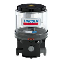
The intermittent low-level signal uses a contactless
mechanism, comprised essentially of the following parts:
• Stationary reed switch (Fig. 11 to 13/1) in the reservoir
bottom
• Mobile baffle plate (Fig. 11 to 12/2) connected to the
stirring paddle, with a magnet (Fig. 11 to 13/3) and a
cam (Fig. 12/4)
Fig.
Perspective view
Functional description of the intermittent low-level
signal
1 When the reservoir is filled with a lubrication grease
that is suitable for the intermittent low-level signal, and
the pump is running, the baffle plate (Fig. 11 to 12/2) is
deflected outwards by the resistance of the lubrication
grease.
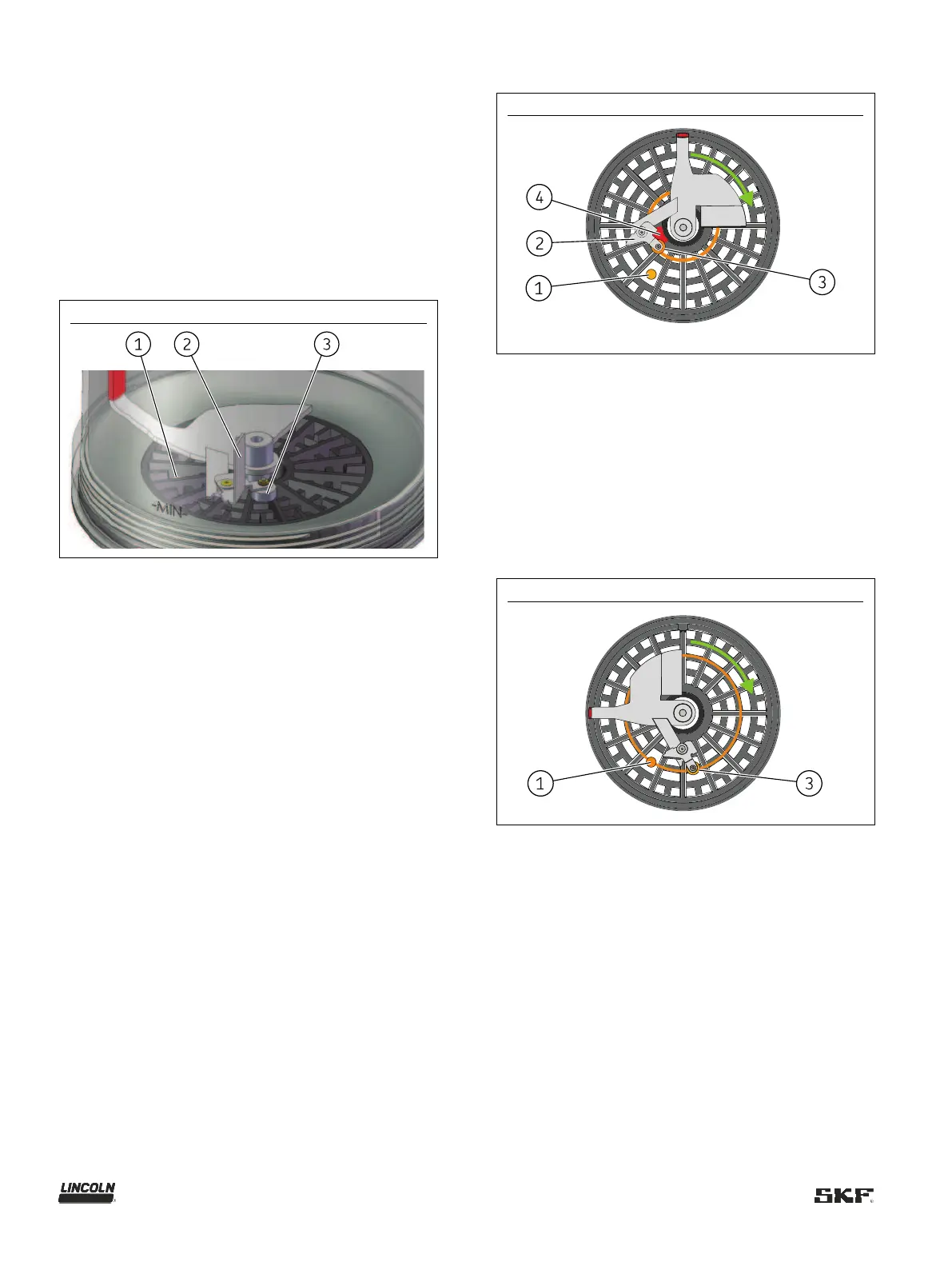
2 As a result, the magnet (Fig. 11 to 13/3) connected to
the baffle plate moves along its inner circular path
(Fig. 12), which means that it cannot trigger a pulse on
the reed switch (Fig. 11 to 13/1).
3 During each revolution, a cam (Fig. 12/4) forces the
magnet and the pivot-mounted baffle plate back out
onto the outer circular path (Fig. 13)
4 After passing the cam, the resistance of the lubricant
pushes the baffle plate and the magnet back inwards,
onto the inner circular path.
Fig.
Magnet on inner circular path
5 When the lubricant level in the reservoir drops so far
that the resistance of the lubrication grease is no
longer enough to deflect the baffle plate
(Fig. 11 to 12/2), the magnet (Fig. 11 to 13/3) stays on
the outer path, triggering a pulse during each revolution
as it slides over the reed switch (Fig. 11 to 13/1).
6 If the magnet (Fig. 11 to 13/3) moves over the reed
switch (Fig. 11 to 13/1) on the outer circular path six
times during one work cycle, a low-level signal is output
directly on the pump's signal connection.
Fig.
Magnet on outer circular path