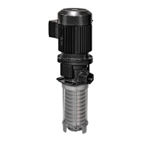
52
6.9.1 Possible settings of the lubrication time and pause time for control circuit board V10-
V23
Table
Setting of the lubrication and pause times
Position of the rotary switch
(blue)
Position of the rotary switch
(red)
Lubrication time in seconds*
Lubrication time in minutes *
* The time values for the lubrication time and pause time are set at the factory using the rotary switches and jumpers on the
control circuit board. If possible, the operator should not change the position of the jumpers.
NOTICE
Impairment of pump function
Never turn the rotary switches to the “0” position. This position is intended solely for the purposes of the
manufacturer.
In the “0” position, the pump works with its factory settings and an error is displayed on the right-hand LED of the
control circuit board.
If the pause/operating time is controlled via the remote contact (terminal 15, e.g., vehicle ignition), correct functioning
requires a certain signal duration. The signal duration required in each case can be derived from the set pause time:
the signal duration must have the same value as the set pause time but in the next smaller unit. Example: Pause time
= 20 minutes - signal duration at least 20 seconds.
If this signal duration is not reached, the pause/operating time must be recoded to maintain the same absolute
lubrication volume over time. Example: setting (in minutes) 5 (blue) / 5 (red) is equivalent to the setting 1 (blue) / 1
(red), resulting in lubricant being supplied more often but in smaller volumes. Experience has shown that this
lubrication method is better than the method of supplying greater volumes of lubricant less often.
6.9.2 Factory settings of the lubrication time and pause time for control circuit board V10-
V23
Table
Factory settings of the lubrication and pause times