73
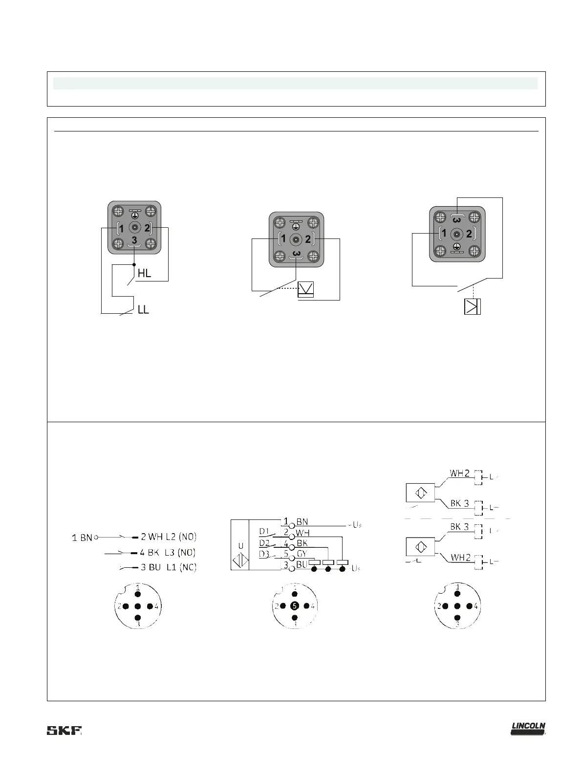
15.1.1 Connection diagram of the signal line on the reservoir cover
The signal line can be connected using a PG9 screwed gland on the pump housing.
The signal line can be connected using a PG9 screwed gland on the pump housing.
Fig.
Lubrication grease, XBx reservoir
Reed switches for full and low-level
signal
Lubrication oil, YLxx reservoir
Float switch for low-level signal
Lubrication grease (special design)
Reed switch for low-level signal
Diagram shows unactuated state, HL = full signal, LL = low-level signal
Lubrication grease (XPxx reservoir)
Actuating rod for full—low-level—
Lubrication grease (BIxx reservoir)
Ultrasonic sensor for full and low-level
signal with inverted signals
Lubrication grease (BKxx reservoir)
Capacitive sensor for low-level signal
Electrical data: see
section 4.6 Technical
data, Ultrasonic sensor
Electrical data: see
section 4.7 Technical
data, Capacitive sensor