64
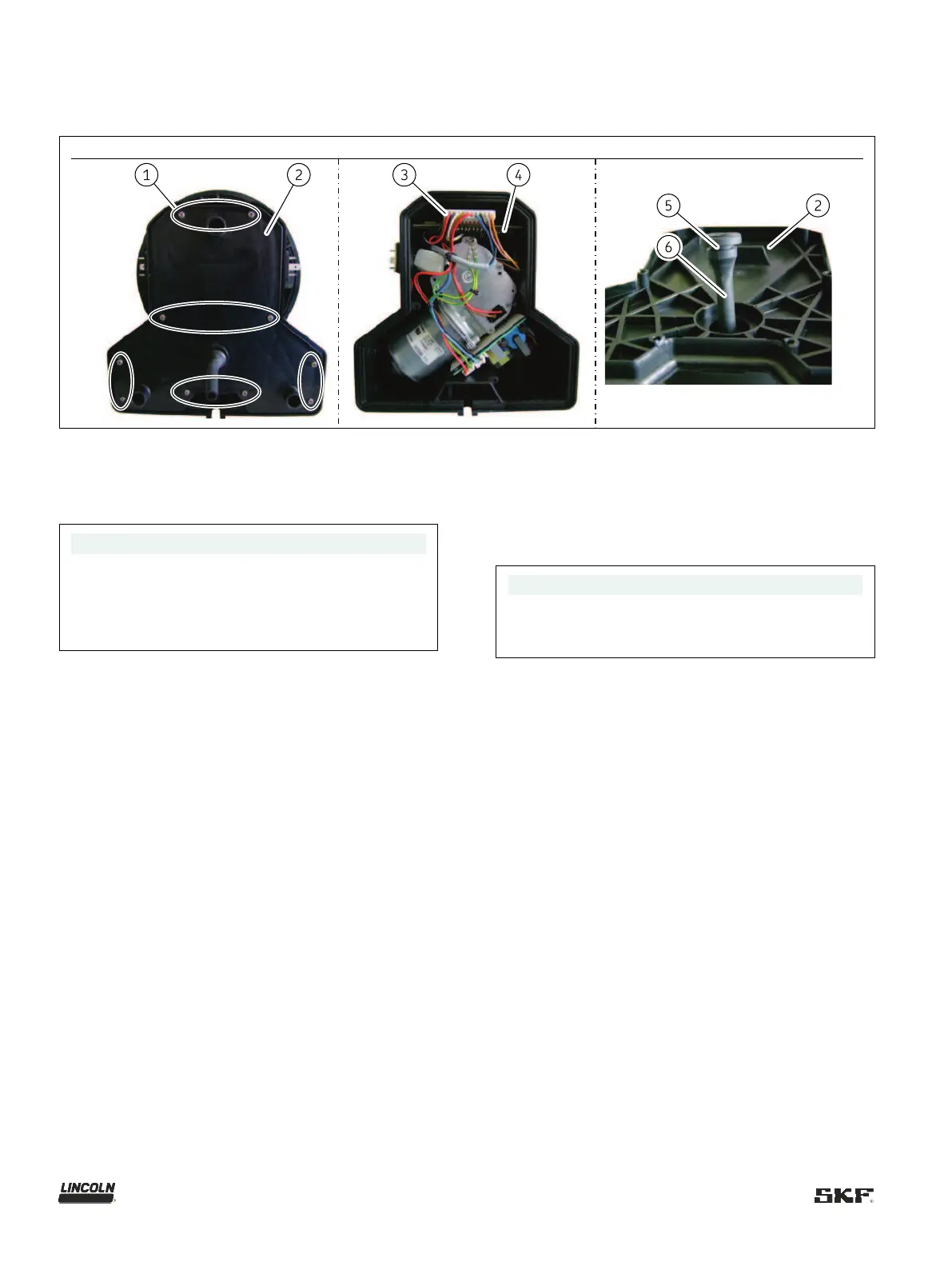
12.2 Replacing the control circuit board
Fig.
Replacing the control circuit board
Screws (10×) for lower housing cover
Housing cover
Plug on the control circuit board
Control circuit board
Groove on the dewatering hose
Dewatering hose
NOTE
The work should be done at room temperature if
possible. Very low temperatures could make
replacement difficult. To make it easier to replace the
control circuit board, tilt the pump into a horizontal
position.
Proceed as follows to replace the control circuit board:
1. Check that the new control circuit board matches the
documentation and the intended use.
2. Take protective measures against electrostatic
discharge.
3. Remove the screws (Fig. 40/1) from the housing cover
(Fig. 40/2).
4. Removing the housing cover
5. Pull the plugs (Fig. 40/3) out of the control circuit board
and pull the control circuit board (Fig. 40/4) out of the
two side guide rails.
6. Make a note of any altered jumper positions and rotary
switch settings and transfer them to the new control
circuit board.
7. Place the control circuit board in the side guide rails
and carefully push it down.
8. Re-insert the plugs.
9. Guide the dewatering hose (Fig. 40/6) through the
housing cover (Fig. 40/2) from the rear until its
groove (Fig. 40/5) engages securely in the housing
cover
10. Place the housing cover on the pump housing and
install it again with the screws
– Tightening torque 0.6 Nm ±0.1 Nm [0.44 ft.lb.
±0.01 ft.lb.]
11. Install the pump at the place of use again.
– Installation and start-up at the place of use should be
done as described in the Assembly chapter.
Checks after replacing the control circuit board
NOTE
An electrical inspection in accordance with
EN
60204-
1 must be performed after the replacement
of the control circuit board.
Archiving
The scope and results of the inspection after replacement
of the control circuit board must be recorded in writing
and given to the party responsible for operation of the
machine, for archiving.