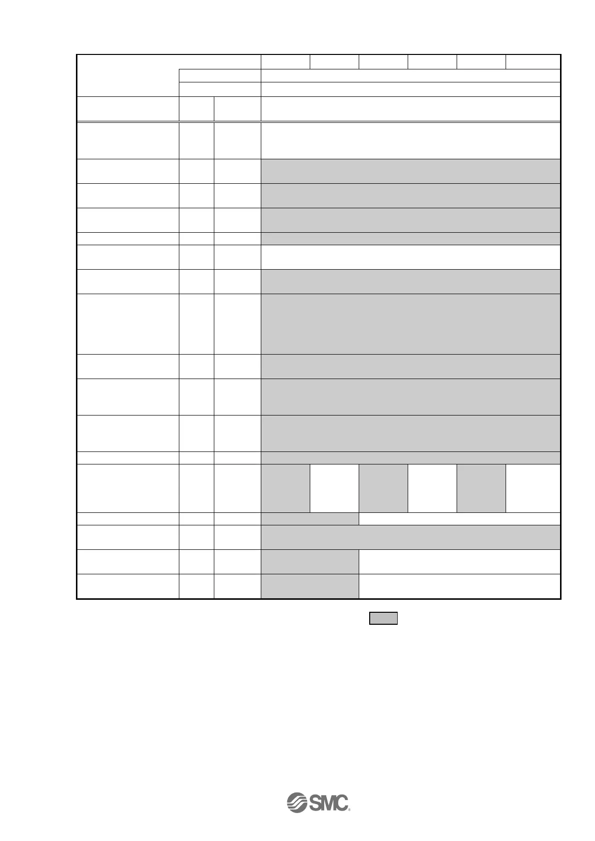
EasyManuals Logo
Home>SMC Networks>Servo Drives>LECSA Series

SMC Networks LECSA Series User Manual

SMC Networks LECSA Series
96 pages
To Next Page IconTo Next Page
To Previous Page IconTo Previous Page
Page #29 background imageLoading...
Page #29 background image
- 27 -
Series
LEFB25
LEFB25U
LEFB32
LEFB32U
LEFB40
LEFB40U
Lead symbol
S
Lead
54
Parameter *1,*2
Para
No
Initial
value
Recommended value
Number of command
input pulses per
revolution
*3.
PA05
100
100
Electronic gear
numerator *3.
PA06
1
100 (Positioning mode: 10)
Electronic gear
denominator *3.
PA07
1
54
Feel length multiplication
(STM) (Multiplier)
PE02
0000
0000 (<1000 stroke)/0001 (>1000 stroke)
Home position return type
PE03
0010
□□□3 (Stopper type)
Home position return
direction
PE03
0010
□□1 (Motor side)
Home position return
Speed (rpm)
PE04
500
33
Home position
return/JOG operation
Accelerationeration/Decel
eration time constants
(msec)
PE07
100
2700
Home position return
position data (μm)
PE08
0
-3000 (<1000 stroke)/-300 (>1000 stroke)
Stopper type home
position return
stopper time (msec)
PE10
100
200
Stopper type home
position return torque
limit value (%)
PE11
15
30
Regenerative option
PA02
000
000 (Non)/002 (LEC-MR-RB-032)
Rotation direction
selection
PA14
0
1 (+
Counter
motors
side)
0 (+
Counter
motors
side)
1 (+
Counter
motors
side)
0 (+
Counter
motors
side)
1 (+
Counter
motors
side)
0 (+
Counter
motors
side)
Adaptive tuning mode
PB01
000
002
000
Load to motor inertia
moment ratio
PB06
7
50
Machine resonance
suppression filter 1
PB13
4500
400
4500
Notch shape selection
1
PB14
000
030
000
Parameter setting required.
Differs to initial value
*1. Parameter is set to the recommended value. Please set parameter according to customer application.
*2. Mechanical resonance may occur depending on the shape or mounting orientation of the work piece. Please change
this parameter during initial configuration.
(Parameter initial configuration Set the recommended parameter value Operation start)
*3. Other than positioning mode: Actuator travel distance at 10 [μm/pulse] per pulse.
Positioning Mode: Minimum actuator travel distance of 1[μm].

Table of Contents

Questions and Answers:

Question and Answer IconNeed help?

Do you have a question about the SMC Networks LECSA Series and is the answer not in the manual?

SMC Networks LECSA Series Specifications

General IconGeneral
BrandSMC Networks
ModelLECSA Series
CategoryServo Drives
LanguageEnglish