Prime - 600
20
Preparing optional accessories.
The ammeter clamp, supplied as an optional accessory by EuroSMC, will be
connected to the “Clamp” connections.
The temperature optical sensor, supplied as an optional accessory by EuroSMC,
will be connected in the “T Sense” connector.
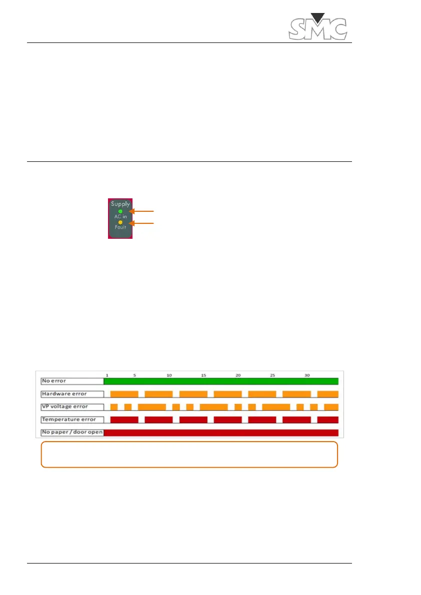
TURNING ON THE SYSTEM
Apply the power switch of your Prime – 600. You can verify the correct supply
status with the indicators on the supply panel.
The green AC in indicator must remain on, from the moment power is supplied
to the unit by activating the power switch. Otherwise, the line power supply and
the input fuse must be reviewed.
If the yellow Fault indicator remains on, this indicates a fault in one or more of
the internal supplies of the equipment or that the line level is too low for the unit
to operate correctly.
The printer indicator must stay on green, from the moment the console of the
equipment is rebooted. Otherwise, this could mean
LED flashing sequence. Each time unit corresponds to 0.5 seconds
 Loading...