92
Scope and Multimeter Operations Using the Scope Module Remotely
i If the Scope Module:
○ Is undocked from the Diagnostic Tool when it is on, or
○ Is exposed to a electro static discharge (ESD) while it is being used remotely
the following will occur:
• Communication between the Diagnostic Tool and the Scope Module will be terminated.
• All current data and settings will be lost.
• An error message (e.g. Meter/Scope Not Found) will display to indicate that
Scope Module communication has terminated.
When communication is reestablished (after a communication loss), the Scope Multimeter
application is restarted and the Scope Multimeter main menu page is displayed.
z To setup the Scope Module for remote operation:
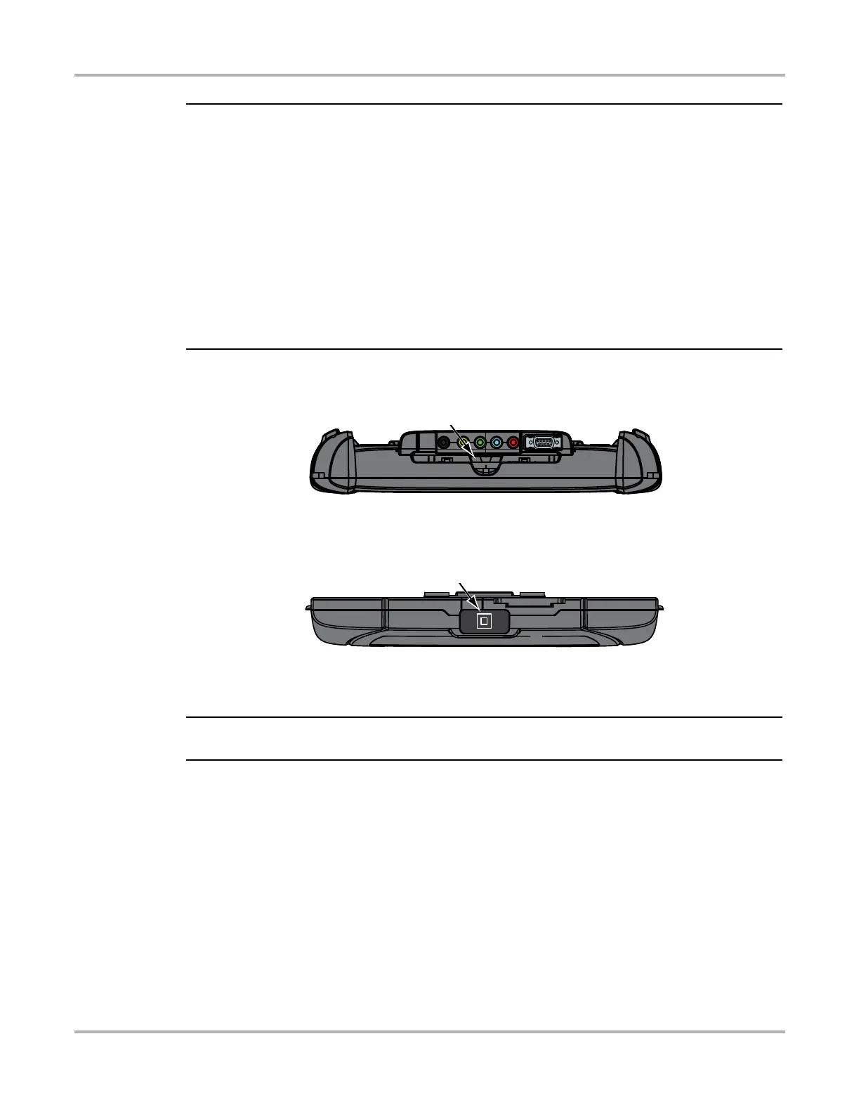
1. Depress the Scope Module release tab located on the top of the Diagnostic Tool (Figure 8-1).
Figure 8-1 Scope Module release tab
2. Slide the Scope Module off of the Diagnostic Tool.
3. Locate the USB jack on the bottom of the Scope Module (Figure 8-2).
Figure 8-2 Scope Module USB jack location
4. Connect the square end of the USB cable to the jack on the Scope Module.
i When used remotely, the M4 must be connected to a USB jack on the diagnostic tool.
5. Connect the rectangular end of the USB cable to a USB port on the Diagnostic Tool.
The Scope Module is now ready for remote use.