64
Scan Module Operation Troubleshooting
5.5.3 Checking Scan Module Hardware Status
Verifying the Hardware Status is always the first step in troubleshooting a wireless connection
issue.
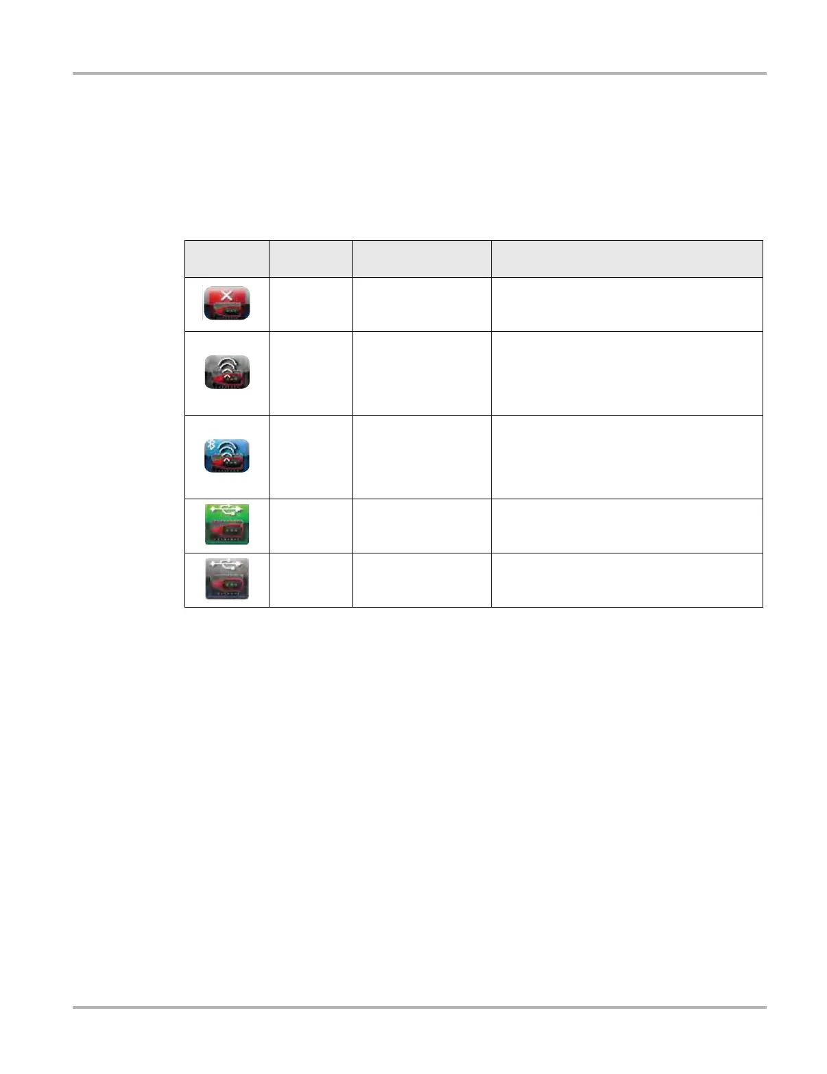
The Hardware Status indicators in the lower-right corner of the Home screen provide a quick
reference to wireless operations. The background color of the status indicator icon represents the
condition of the wireless connectivity to that device. Icon status is shown in the table below:
The three light emitting diodes (LEDs) on the faceplate of the Scan Module let you know at a
glance whether or not there is an active connection between the two modules. The two green
LEDs (Vehicle Power and Bluetooth) both flash on and off when the Scan Module and diagnostic
tool are actively communicating through a wireless connection. The red Communication LED
flashes on and off when the Scan Module is performing an internal self test, and is illuminated
continuously if a failure is detected (Figure 5-6).
Hardware
Icon
Background
Color
Condition Action
Red Not Paired
Pair the Scan Module to the diagnostic tool. See
Pairing The Scan Module on page 59 for
instructions.
Grey
Paired, but Not
Communicating
You may have moved out of range. Move the
diagnostic tool closer to the Scan Module to
reestablish communications. If connectivity is
not restored, perform the
Recovery
Procedure
on page 66.
Blue
Paired and
Communicating
Hardware status is good and Bluetooth should
be functional. Verify that the green Bluetooth
LED on the front of the Scan Module is flashing.
If there is no connectivity, perform the
Recovery Procedure on page 66.
Green USB Cable Connected Indicates the USB cable is connected.
Gray
USB Cable Not
Connected
Indicates the USB cable is not connected or
connected but not allowing communication