96
Scope and Multimeter Operations Getting Started
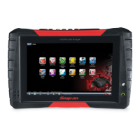
Channel 1 Lead
Figure 8-4 Yellow Channel 1 Lead
The shielded yellow lead is used for Channel 1 (Figure 8-4) and other channel connections that
need additional grounding. The lead color matches the color of socket 1 on the Scope Module and
the color of trace 1 on the test screens.
This yellow lead includes a black, right-angle, common ground plug and a black, stackable,
common ground plug. The non-stackable ground plug always connects to the ground (GND) jack
on top of the Diagnostic Tool. The stackable ground plug is used for connecting additional leads,
such as the Channel 2 Lead or the Secondary Coil Adapter Lead, that require grounding. The
stackable lead grounds through the non-stackable lead and does not need to be connected to the
jack on the Diagnostic Tool.
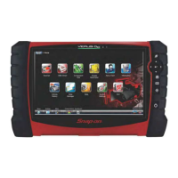
Channel 2 Lead
Figure 8-5 Green Channel 2 lead
The shielded green lead (Figure 8-5) is used for Channel 2. The lead color matches the color of
socket 2 on the Scope Module and the color of trace 2 on the test screens. This green lead
includes a stackable, black, right-angle ground plug.
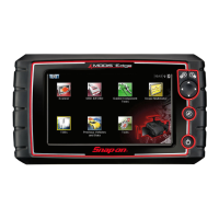
Channel 3 Lead
Figure 8-6 Blue Channel 3 lead
The non-shielded blue lead (Figure 8-6) is used for either Channel 3 or Digital Meter minus (–).
The lead color matches the color of socket 3 on the Scope Module, as well as the color of trace 3
on the test screen.
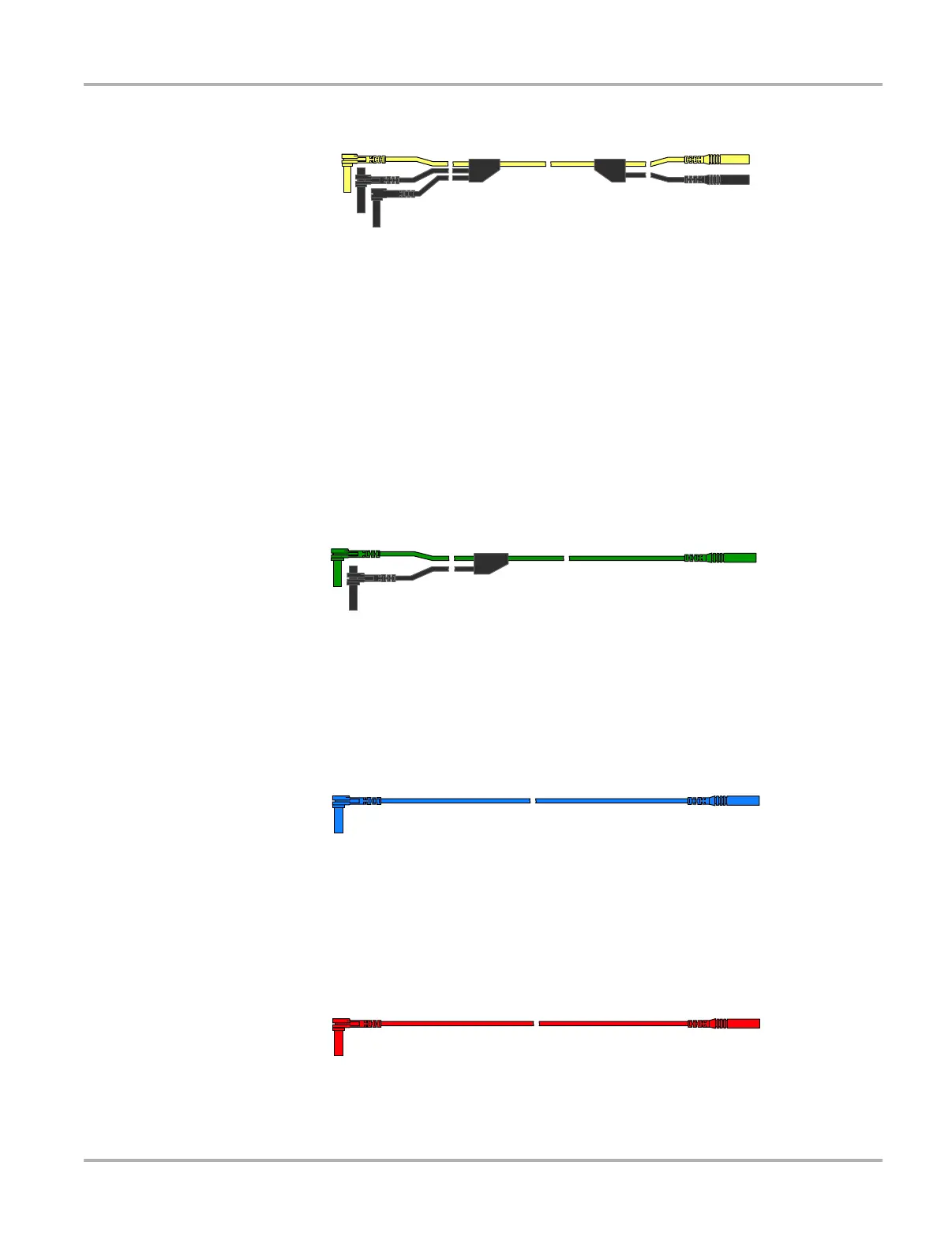
Channel 4 Lead
Figure 8-7 Red Channel 4 lead
 Loading...