15
v1.01
M215SC User Manual Setting Up
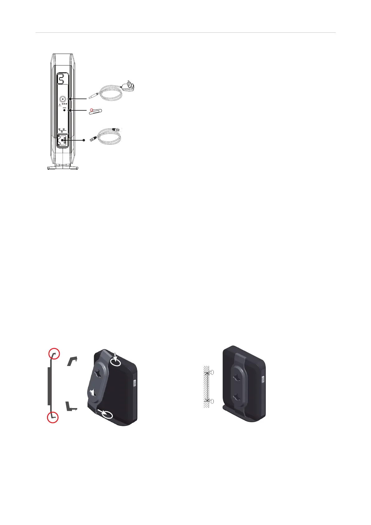
Use only
Supplied
Adapter
DC 5V
RESET
(1), (2)
Network &
Power over Ethernet
Reset key
(1)
If no PoE available
(2)
Not included in delivery
Fig. 1
Standing Unit
1. Connect the Ethernet cable to the RJ45 jack on the side of the device (see Fig. 1, above) and to your network
router or switch.
2. If a power adaptor is necessary, connect it to the coaxial connector on the side of the device (see Fig. 1,
above) and to an electrical wall outlet.
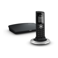
Wall Mounting
Prior to mounting the device on the wall, you must attach the wall bracket to the back of the base station. The
bracket has two holes for hanging the unit on two screws or hooks on a wall.
Note: Screws/hooks and wall anchors are not included in the delivery. Use screws and wall
anchors suitable for your wall. Select screws with heads of a minimum of 5 mm (0.1969") in
diameter.
1. Attaching the wall bracket.
Insert tab
in slot
in slot
50 mm
(1.969")
Fig. 2 Fig 3
a. Insert the short tab (Fig. 2, step 1) on the bracket in the slot at the top of the base station.
b. Insert the longer tab (Fig. 2, step 2) on the bracket in the slot in the base station's footstand until it
clicks into place. Check to make sure the bracket is securely attached to the base station.