Paramount GEM User Guide
56 | P a g e
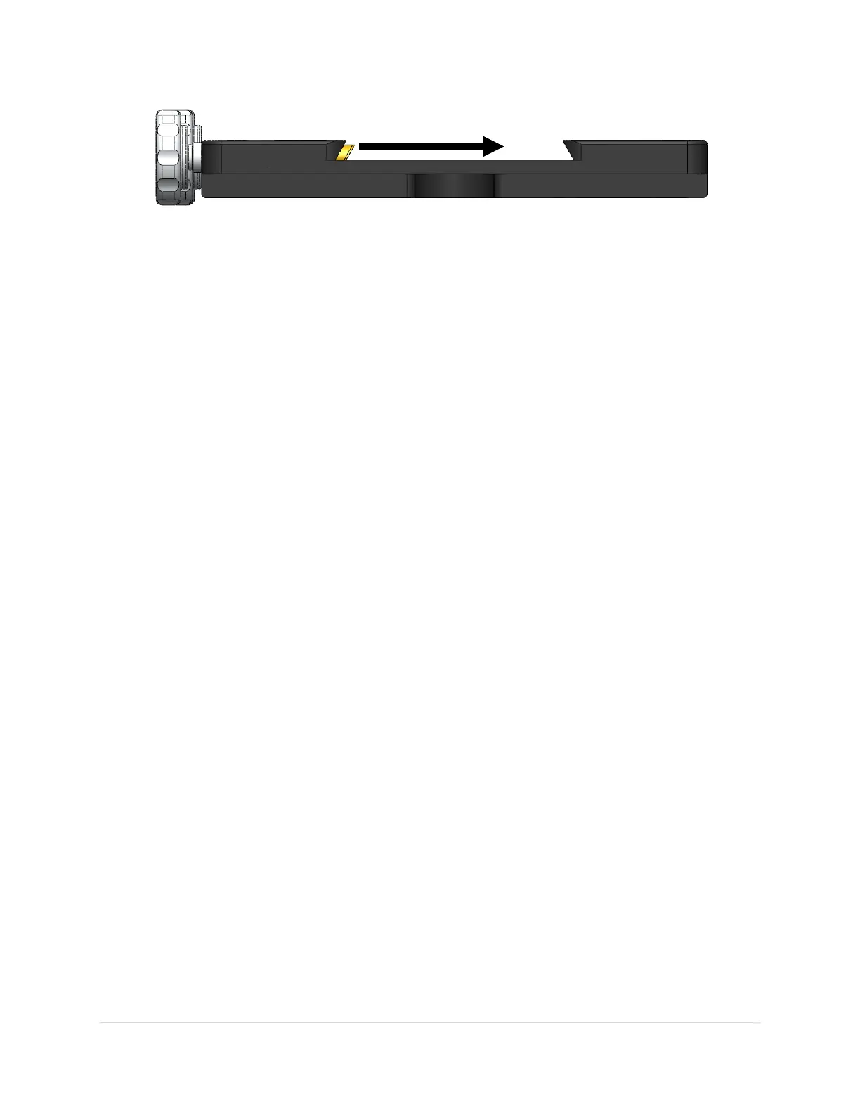
Figure 21: The brass plunger compresses the male dovetail against the opposite side (from left to right in the above diagram).
3. Tighten each Versa-Plate knob by hand until the brass plungers securely hold the dovetail in place.
While tightening the knobs, push the telescope dovetail in the same direction as the advancing
brass plungers to make sure the dovetail plate is securely compressed against opposite side of
the dovetail wedge (Figure 21). Also make sure the male dovetail plate is securely captivated by
at least three of the four Versa-Plate Knobs before letting go of the telescope or testing balance
in declination. Securing a heavy or expensive payload with fewer knobs may not be sufficient to
hold the telescope in place. The length of the male dovetail varies by manufacturer. For best
results and when the length of the male dovetail permits, always tighten all of the knobs to the
hold the dovetail securely in place.
4. Test the declination axis balance, then slide the telescope as needed.
5. After the telescope is balanced and the knobs are hand tightened, re-secure each knob by
inserting a 1/4-in hex wrench and tighten it an additional one-quarter turn only. Do not over
tighten these knobs or the internal threads can be damaged. Note that when two or three of
the knobs are “hand tight”, the dovetail will not slide. The final 1/4 turn with the hex wrench
ensures that your heavy and expensive payload is mounted securely and will not move when the
mount slews to different mechanical orientations.
Versa-Plate Mounting Positions
The Paramount MYT, MX, and ME Versa-Plate can be mounted to the top of the declination axis in four
different positions to move the balance point for different payloads. The gray circles in Figure 22
represent the top of the declination axis at each mounting position.
If your payload is “camera-end heavy,” attach the Versa-Plate at the forward most position so that the
payload can be more easily balanced. Remove the six 1-inch socket head cap screws (SHCS) using a 3/16-
in hex wrench, then adjust the position of the Versa-Plate accordingly. The mounting position depends
on your equipment, so there may be a bit of trial and error to find the optimal position. The four SHCS
should be tightened snugly so that the Versa-Plate cannot wiggle or shift when carrying the payload, but
not overly tight.