Paramount GEM User Guide
58 | P a g e
Standard Versus Wide Mounting Versa-Plate Orientation
The Paramount is shipped with the Versa-Plate in the standard orientation. In this orientation, the optical
axis of the telescope is parallel to the long axis of the Versa-Plate. In the wide orientation, the Versa-Plate
is rotated 90 degrees from the standard orientation, so that the telescope’s optical axis is perpendicular
to the long axis of the Versa-Plate. This orientation can accommodate side-by-side telescopes.
The Instrument Panel is attached to the end of the Versa-Plate. Typically, you will want
to mount the optical tube assembly to the Versa-Plate so that the eyepiece or camera
end is as close to the Instrument Panel as possible. Doing so offers the shortest cable
route between powered accessories that are mounted to the draw tube and the power
ports on the Instrument Panel.
The standard Versa-Plate mounting configuration works well for Schmidt-Cassegrain,
Ritchie-Chretien, and refracting telescopes where the “business end” naturally places
equipment near the Instrument Panel.
For Newtonian telescopes and other optical designs, where the camera and other
accessories are located toward the “front” of the telescope, the Instrument Panel can
be attached to the opposite end of the Versa-Plate.
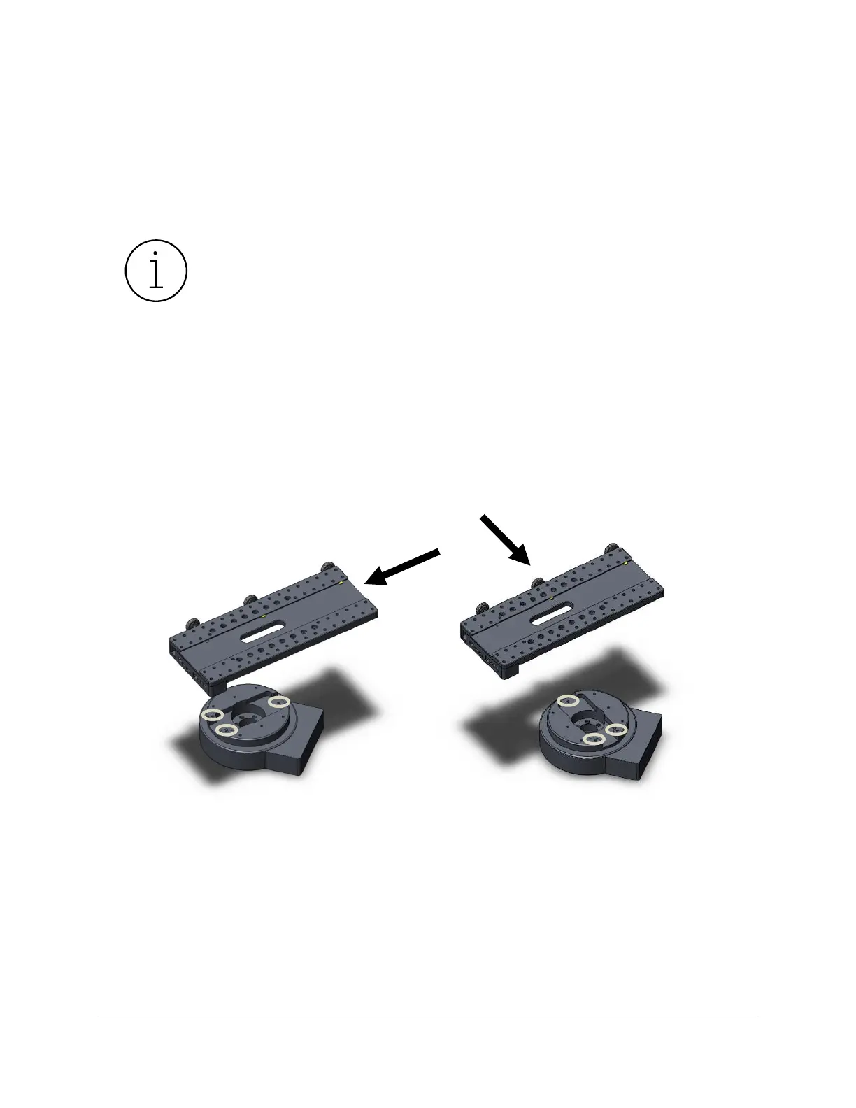
Figure 24: The standard (left) and wide (right) Versa-Plate mounting orientations for the Paramount MX.
Figure 24 shows one standard and one wide orientation of the Versa-Plate, relative to the top of the
Paramount MX declination axis. For each orientation, the black arrow shows the direction that incoming
light from stars will pass through the telescope.
When mounting the Versa-Plate on the Paramount MX, pay very close attention to the mounting holes
on the top of the declination axis. The three circled holes in Figure 24 form a triangle that must point
toward the stars, or, in the opposite direction of the OTA’s incoming light.