22
5�2 Connection area
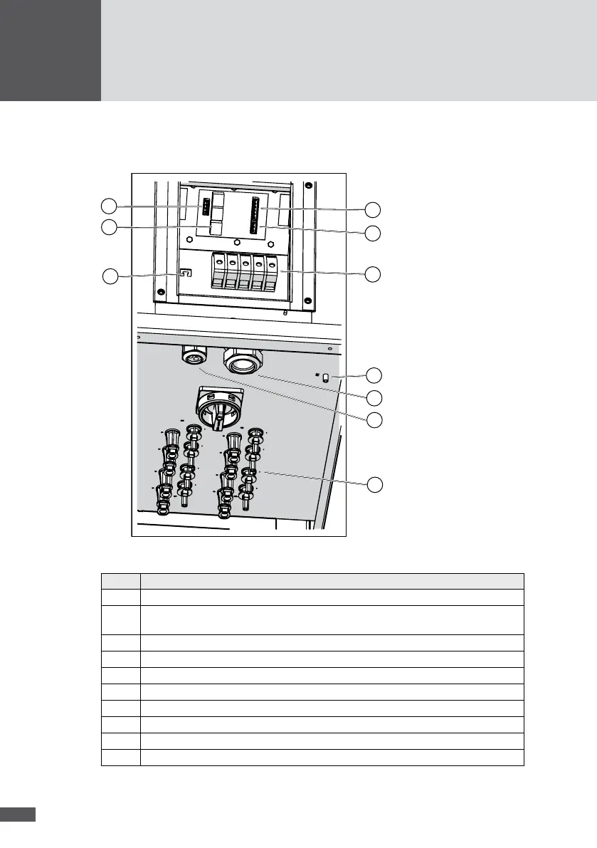
All terminals and cable glands of the inverter are shown in Figure 12.
1
2
3
4
5
7
6
9
10
8
Figure 12 Connection area
No� Description
1 DC terminals (MC4 compatible plug-in terminals)
2 "COMM" multiple cable gland for communication cables (network connections, status
signaling contacts, external shutdown)
3 "AC mains" cable gland for the AC input conductor
4 M5 threaded "PE" bolt for the connection of the second protective conductor (optional)
5 AC terminals (screw terminals)
6 External shutdown (plug-in terminal)
7 Status signaling contacts (plug-in terminal)
8 RS485 (plug-in terminal)
9 Ethernet and RS485 communication sockets (RJ45)
10 Cable grips for restraining the cable (for the communication cables)