en
23
5�3 Connecting the inverter to the mains
DANGER!
Fatal electric shock hazard!
Make sure the AC input conductor is not live during connection work.
Connection conditions
Comply with the connection conditions set by the grid operator.
M40 cable gland; suitable for cable Ø: 24 to 33 mm
Connection type: screw terminals (UWV 25)
Permissible conductor cross sections:
– exible conductor (with or without conductor sleeve): max. 25 mm
2
– rigid conductors: max. 35 mm
2
The protective conductor of the AC input conductor should be cut at least 30 mm
longer than the other conductors.
The AC input conductor must be fused. Minimum conductor cross sections and sug-
gested mains fuses:
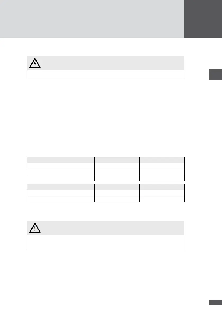
Minimum conductor cross sections 30HT4 32HT4
Phases L1, L2, L3 10 mm
2
10 mm
2
Neutral conductor N 4 mm
2
4 mm
2
Protective conductor PE 10 mm
2
10 mm
2
Recommended mains fuses 30HT4 32HT4
Nominal current 63 A 63 A
Characteristics C C
Make sure the ambient temperatures for the mains fuses specied by the producer
are not exceeded.
WARNING!
Fatal fire risk!
Provide separate fuses for each inverter.
Do not connect any loads between the inverter and the mains fuse.
If you use external residual current devices (RCDs), use the type B RCDs with a nom-
inal fault current of 100 mA. For PV plants with large stray current capacities, the
RCDs to be used should have a nominal fault current capacity of 300 mA.
Procedure
1. Remove the cover of the inverter as described in section 5.1.
2. Thread the AC input conductor through the cable gland.