en
29
Note
The RJ45 connectors can be pulled through the multiple cable gland.
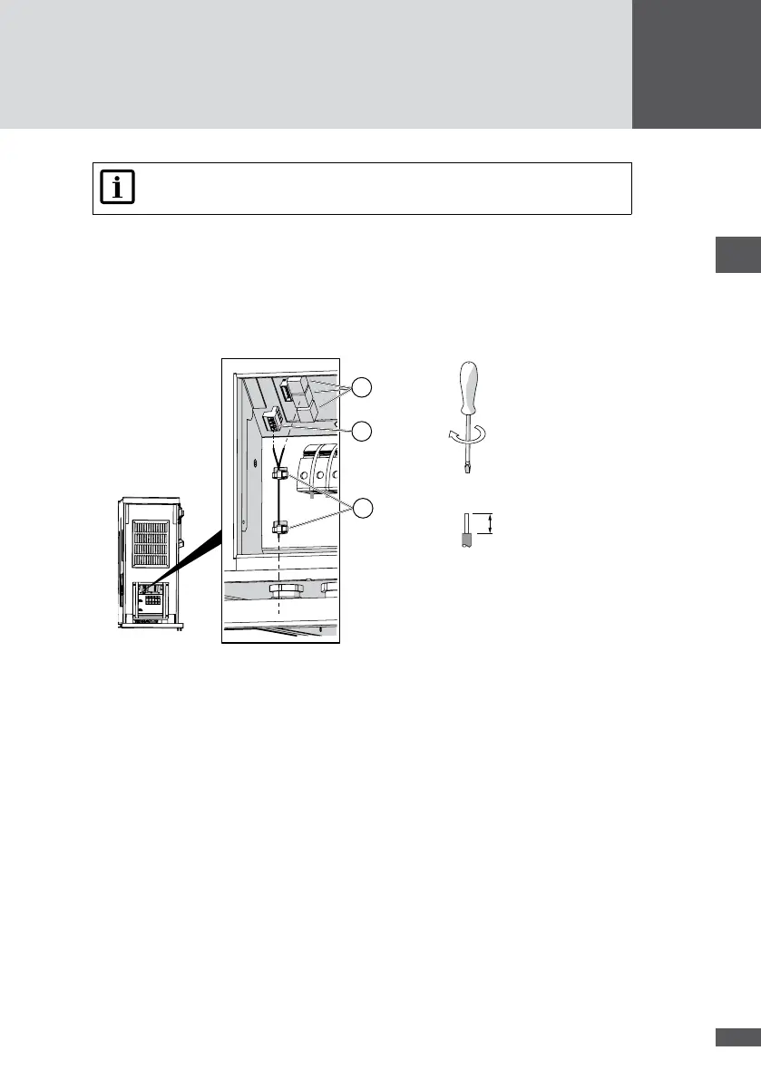
3. Plug the network cables into the RJ45 sockets (Figure 19/No.1) and check that the
connection is locked.
4. RS485 terminal connection (Figure 19/No.2): connect the RS485 network cable as
follows:
– Wire stripping length: 7 mm
– Tightening torque: 0.5 to 0.6 Nm
0.5 … 0.6 Nm
M3
7 mm
3
2
1
Figure 19 Network connection
5. Use cable ties to attach the cables to the housing grips (Figure 19/No. 3).
6. Close off the unused apertures in the multiple cable glands using the locking pins (No.
8 in Section 4.3).
7. Tighten the multiple cable gland (wrench size: 34 mm).
8. Fit the cover of the inverter.
5�6 Connecting status signaling contacts (optional)
The congurable status signaling contacts are used for the remote monitoring of the
inverter. Both power units (MPP tracker 1/2 and MPP tracker 3/4) can be monitored indi-
vidually using a status signaling contact. When the external deactivation is used (see
Section 5.7) the status signaling contacts cannot be used.
The status signaling contacts can be congured, see Section 6.4.4.