28
12
3
4
A
GND
15 V
B
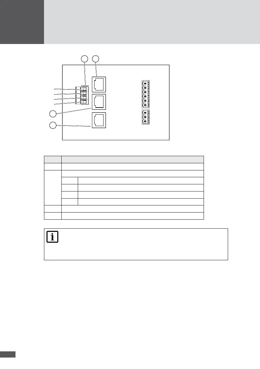
Figure 18 Network connections
No� Description
1 RJ45 socket RS485
2 RS485 plug connection
B Bus B
15 V 15 V network input
GND Network input ground connection
A Bus A
3 RJ45 socket RS485
4 RJ45 socket Ethernet
Note
You will nd further details about data communication in the technical infor-
mation "MaxComm network". You can download this document from our web-
site at: www.solarmax.com; Downloads/Data Communication/MaxComm.
Connection conditions
Connection types: 3 x RJ45 sockets / 4-pole plug (included in the delivery)
Suitable conductor cross sections (plug connector): 0.25 to 2.5 mm
2
Multiple cable gland; usable cable Ø: 5.5 to 7.0 mm
You should use shielded network cables (cat. 5)
Procedure
1. Remove the cover of the inverter as described in section 5.1.
2. Thread the network cables through the multiple cable gland.