en
33
0.5 … 0.6 Nm
M3
7 mm
3
1
2
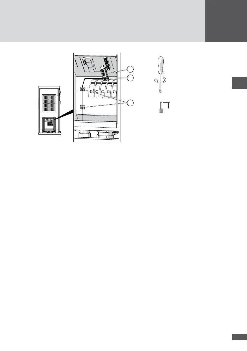
Figure 23 Connecting the external shutdown
4. Plug in the 3-pole connector.
5. Plug in the 6-pole connector (Figure 23/No. 1) in order to cover the open contacts.
6. Check that the NA21 and NA22 contacts are bridged (Figure 22/No. 1).
7. Use cable ties to attach the cables to the housing grips (Figure 23/No. 3).
8. Close the unused apertures in the multiple cable gland using the locking pins (No. 8
in Section 4.3).
9. Tighten the multiple cable gland (wrench size: 34 mm).
10. Fit the cover of the inverter.
5�8 External output control (optional)
The MaxWebxp data logger and its MaxRemote extension can be used to set the set
values for active and reactive power (e.g. for remote controlled output limitation). The
MaxWeb xp is connected via the Ethernet or via the inverter's RS485 interfaces (see Sec-
tion 5.5), i.e. via a MaxComm network.
You can download the installation instructions for the MaxWebxp and MaxRemote acces-
sory components from our website: www.solarmax.com; Downloads / Data communica-
tion / MaxWebxp.