en
31
M3
7 mm
1
2
3
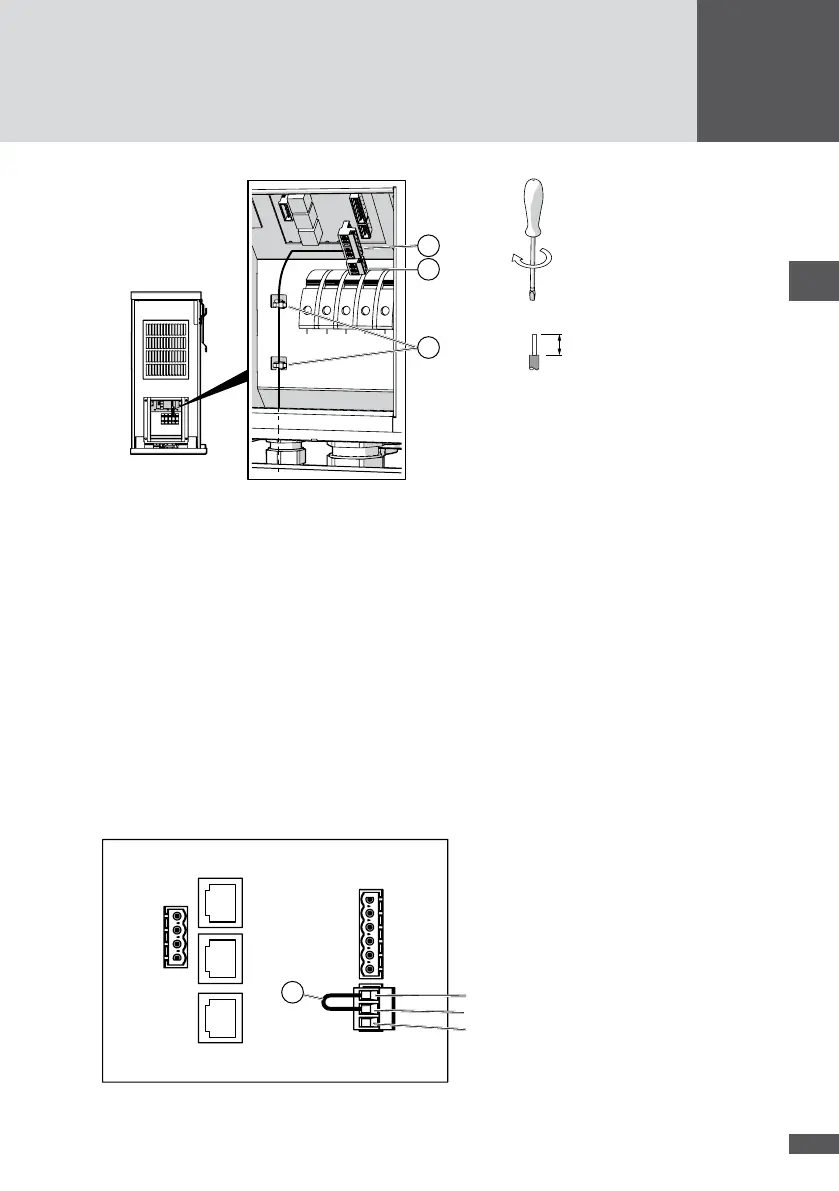
Figure 21 Connecting the status signaling contacts
4. Plug in the 6-pole connector.
5. Plug in the 3-pole connector (Figure 21/No.2) in order to cover the open contacts.
6. Use cable ties to fasten the cables to the housing grips (Figure 21/No. 3).
7. Close off any unused apertures in the multiple cable gland using the locking pins (see
No. 8 in Section 4.3).
8. Tighten the multiple cable gland (wrench size: 34 mm).
9. Fit the cover of the inverter.
5�7 External shutdown (optional)
This interface can be used to connect the inverter to an external grid monitoring system
which can disconnect the inverter from the mains grid from a remote location when this
is needed.
NA21
NA22
NA1
1
Figure 22 External shutdown terminals