30
COM1
NC1
NO1
NC2
COM2
NO2
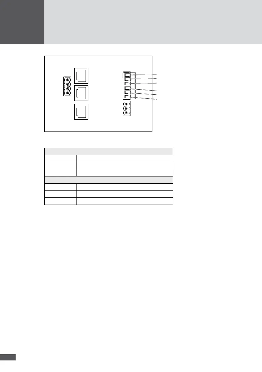
Figure 20 Status signaling contacts
Status signaling contact MPP tracker 1 and 2
NC1 Opens in the case of an error
COM1 Common 1
NO1 Closes in the case of an error
Status signaling contact MPP tracker 3 and 4
NC2 Opens in the case of an error
COM2 Common 2
NO2 Closes in the case of an error
Connection conditions
Connection type: 6-pole connector (included in the delivery)
Connectable conductor cross sections: min. 0.25 mm
2
/ max. 2.5 mm
2
Multiple cable gland; usable cable Ø: 5.5 to 7.0 mm
Max. switching voltage: 250 VAC / 30 VDC
Max. switching current: 1.5 A (no internal fuse present)
Max. cable length: max. 50 m
Procedure
1. Remove the cover of the inverter as described in section 5.1.
2. Thread the cable through the multiple cable gland.
3. Connect the control lines to the 6-pole connector (Figure 21/No. 1) as follows:
– Wire stripping length: 7 mm
– Tightening torque: 0.5 to 0.6 Nm