24
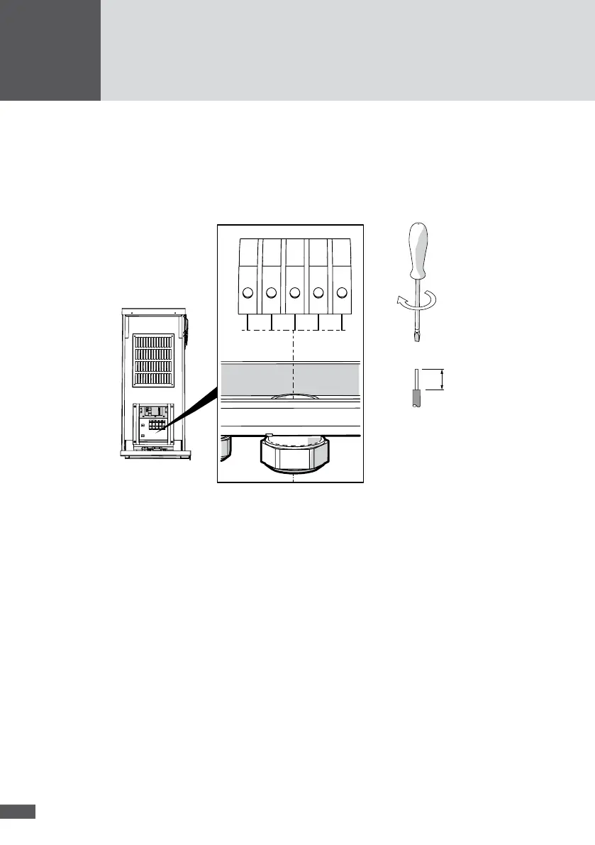
3. Cut back the insulation of the conductor by 19 mm.
4. Connect the wires in the following sequence:
– the protective conductor to the "PE" terminal
– the neutral conductor to the "N" terminal
– the mains phases to the terminals "L1", "L2", and "L3".
– Tightening torque: 4 to 4.5 Nm
L2
L3 PE
N
L1
19 mm
Figure 13 AC connection
5. Check the cable connections for rm seating.
6. Tighten the M40 cable gland.
7. Check the cable strain relief.
8. Connect the second protective conductor (optional):
– Installation sequence (see Figure 14): M5 toothed washer (No. 1), cable shoe (No.
2), M5 washer (No. 3), M5 circlip (No. 4), M5 lock nut (No. 5);
– all xing elements are included in the delivery.