EasyManua.ls Logo

Solartron 1260 - Configuring Analyzer Input Connections

Solartron 1260
295 pages
Print Icon
To Next Page IconTo Next Page
To Previous Page IconTo Previous Page
Loading...
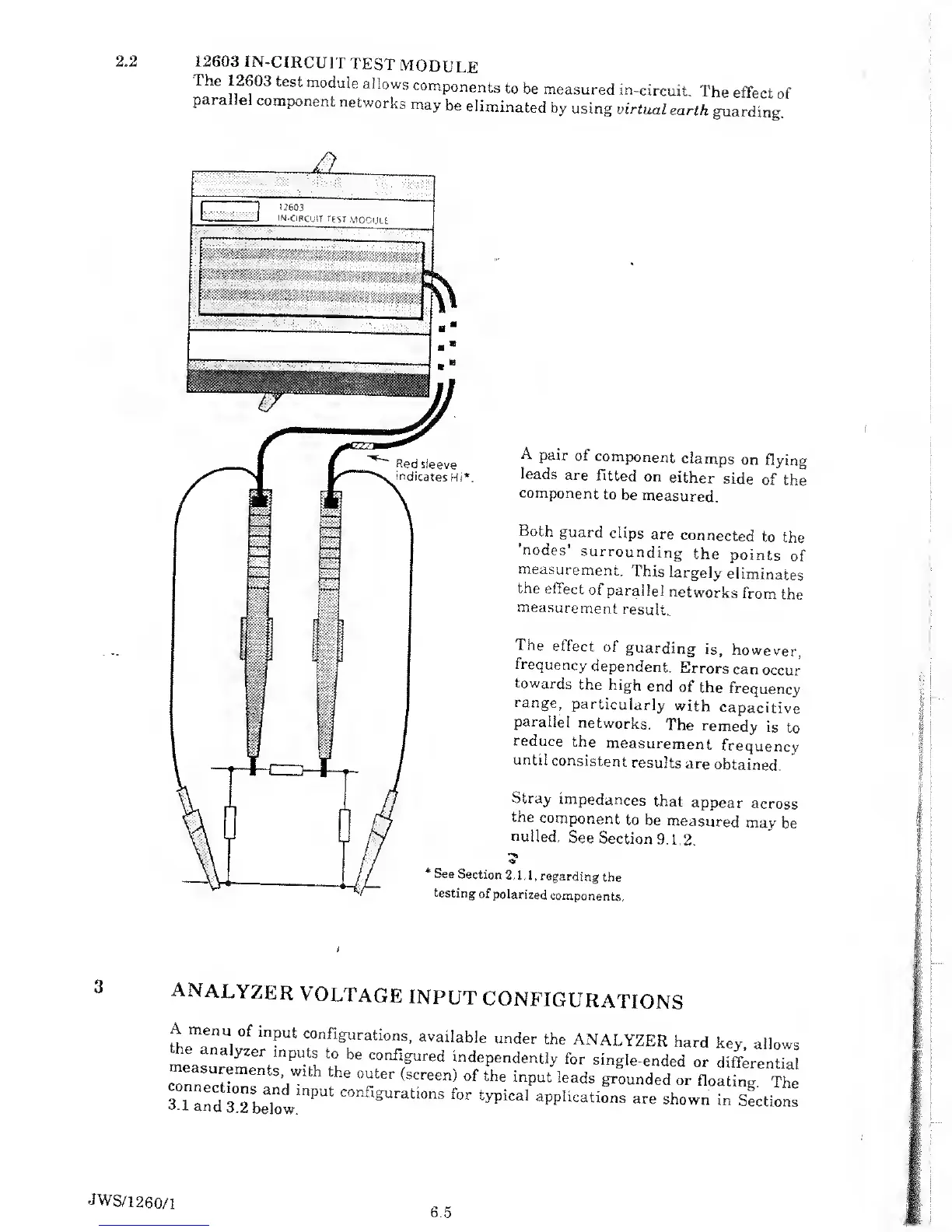
2.2
12603
IN-CIRCUIT
TEST
MODULE
The
12603
test
module
allows
components
to
be
measured
in-circuit.
The
effect
of
para
el
component
networks
may
be
eliminated
by using
virtual
earth
guarding.
H
12603
IN-CIRCUIT
TEST
-MODULE
if
/ %
u;-'
r"
:
'
A
pair of
component
clamps
on
flying
leads
are
fitted
on
either
side
of
the
component
to
be
measured.
Both
guard
clips
are
connected
to
the
’nodes’
surrounding
the
points
of
measurement.
This
largely
eliminates
the
effect
of
parallel
networks
from
the
measurement
result..
The
effect
of
guarding
is,
however,
frequency
dependent.
Errors
can
occur
towards
the
high
end
of
the
frequency
range,
particularly
with
capacitive
parallel
networks.
The
remedy
is
to
reduce
the
measurement
frequency
until
consistent
results
are
obtained.
Stray
impedances
that
appear
across
the
component
to be
measured
may
be
nulled.
See
Section
9.1,2.
*
See
Section
2.1.1,
regarding
the
testing
of
polarized
components.
/
analyzer
voltage
input
configurations
A
menu
of
input
configurations,
available
under
the
ANALYZER
hard
key
allows
he
analyzer
inputs
to
be
configured
independently
for
single-ended
or
differential
conneT
h
Wlth
°Uter
(SCreen)
°f the
!nput
leads
Sanded or
floating
The
3
1
and
3°2
bT
COnflg,JrationS
for
typicaI
applications
are
shown
in
Sections
JWS/1260/1
6.5

Table of Contents

Related product manuals