1
INTRODUCTION
The
instrument
is fitted, as standard, with a GPIB
interface and an
RS423 interface,
for
communication
with
remote devices.
Full
control and data input/output is possible
through the GPIB.
RS423
is intended mainly for data output to a
printer, VDU, etc, but,
if the user is
fully
conversant
with
RS423 protocol, limited
control of the
instrument may, in some
cases, be
possible.
2 GPIB
INTERFACE
The
GPIB Interface conforms
to
the IEEE 488,1978
standard. The complete
standard
is
published
by
the IEEE under the title: "IEEE
Standard Digital
Interface for
Programmable Instrumentation".
A
useful
introduction
to
the theory of the GPIB
is
given
in
the
Solartron monograph: "Plus Bus
-
the
Solartron GP-IB”.
2.1
GPIB CAPABILITY CODE
The GPIB
Interface in the instrument conforms to the
following sub-functions
within
the standard, as listed on the
rear panel:
SHI Source
handshake.
AH1 Acceptor handshake.
T5 Basic
talker,
serial poll, talk only
selectable, unaddressed
if MLA
(My
Listener Address).
TEO
No extended talker capability.
L4
Basic listener,
no listen only
mode, unaddressed if
MTA (My Talker
Address).
LEO No
extended
listener capability.
SRI
Complete
service request capability.
RL1 Complete remote/local capability, with
local lock-out.
PP2 Parallel poll with
local
configuration.
DCl Complete device clear capability, including
selective device clear.
CO No
controller
capability.
DTO No
device trigger
capability.
El Open
collector drivers.
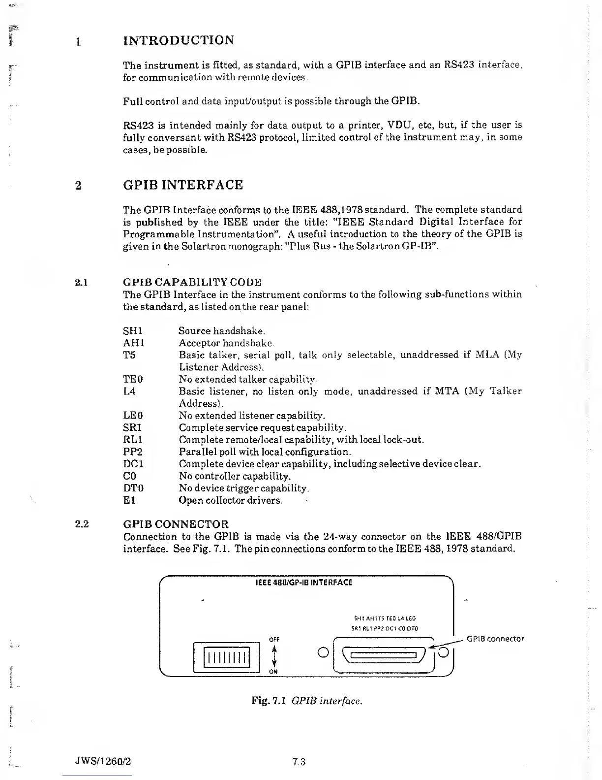
2.2
GPIB CONNECTOR
Connection to the GPIB is made via the 24-way connector
on the IEEE 488/GPIB
interface. See Fig. 7.1. The pin connections conform to the IEEE 488,
1978 standard.
GPIB
connector
Fig. 7.1 GPIB
interface.
JWS/1260/2
7.3