1-18
BVW-55
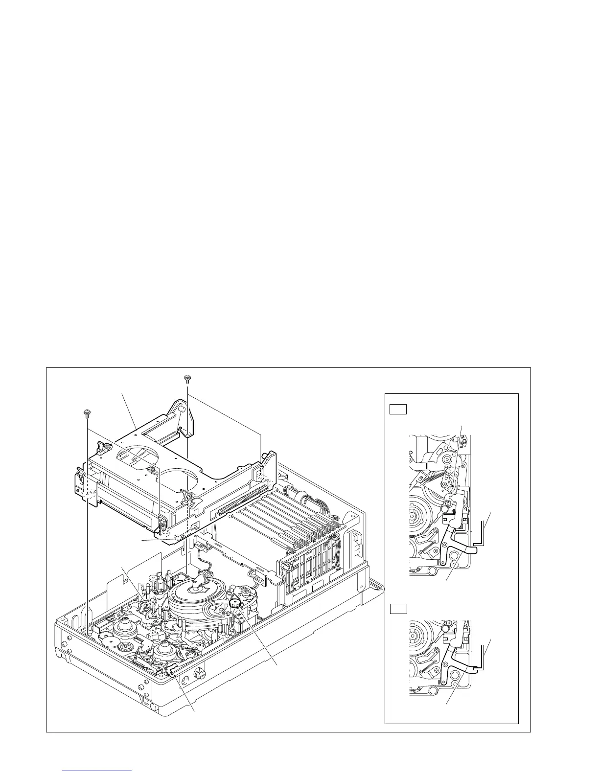
1-7. Removing/Reinstalling the Cassette Compartment
n
When removing or installing the cassette compartment, it is possible for screws to fall into the mechanical
deck assembly. To prevent this, it is recommended to magnetize the screwdriver bit moderately.
1. Make sure the unit is in the unthreading end state. (Refer to Section 1-18.)
2. Remove the upper frame. (Refer to Section 1-6-2.)
3. Remove the four screws of the cassette compartment.
Grasp the cassette compartment by the portion A and lift it out from the mechanical deck assembly.
4. Reinstall the cassette compartment in the reverse order of removal.
m
. At installation, make sure that the release lever of the cassette compartment is in proper alignment
with the eject link assembly as shown in the figure. If the release lever is positioned over the eject
link assembly (for example when the unit is put in the manual eject mode), the eject link assembly
must be aligned. The alignment can be performed in two possible methods:
(1) Turn on the power once and the eject link assembly will return to the proper position
automatically.
(2) Turn the manual eject knob (red) clockwise two or three turns while pushing down until the
reference hole of the function cam comes into sight.
. The screws securing the cassette compartment should be torqued as specified.
Tightening torque: 20 x 10
_2
N.m {2.0 kgf.cm}
1-7. Removing/Reinstalling the Cassette Compartment
Cassette compartment
Mecanical deck
assembly
Release lever
Manual eject knob
Eject link assembly
OK
NG
PSW2 x 5
PSW2 x 5
A
Positioning Alignment
Reference hole
(Function cam)
Release
lever
Release
lever
Eject link assembly
Eject link assembly