6 (E)
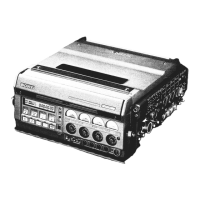
BVW-55
Contents
This manual is organized by following sections.
Section 1 Spare Parts
Describes the exploded views, the mechanical parts list and the electrical parts list.
Section 2 Semiconductor Pin Assignments
Describes the semiconductor pin assignments.
Section 3 Block Diagrams
Describes the block diagrams of overall and each board.
Section 4 Schematic Diagrams and Frame Wiring
Describes the frame wiring and the schematic diagrams.
Section 5 Board Layouts
Describes the board layouts of printed wiring boards.
Section 1 Service Overview
Explains the service information (the removal of PLCC IC, board extension, NV-
RAM, and so on) for this manual (volume 1).
Section 2 Maintenance Mode
Explains menus of the maintenance mode for adjustment.
Section 3 Replacement of Periodic Maintenance Parts
Explains the replacement of periodic maintenance parts and overview for replace-
ment of mechanical parts.
Section 4 Main Parts Replacement
Explains the replacement of mechanical parts (except periodic maintenance parts)
and circuit boards.
Section 5 Tape Path Alignment
Explains the tape path alignment after replacement of parts that are described in
Section 3 and Section 4.
Section 6 Electrical Alignment after Replacement of Periodic
Maintenance Parts
Explains the electrical alignment associated with replacement of parts that are
described in Section 2.
Section 7 Electrical Alignment
Explains the electrical alignment for the maintenance of this unit.
Maintenance manual
part 2 volume 1
(9-967-828- )
Maintenance manual
part 2 volume 2
(9-967-829- )





 To Next Page