1-21
BVW-55
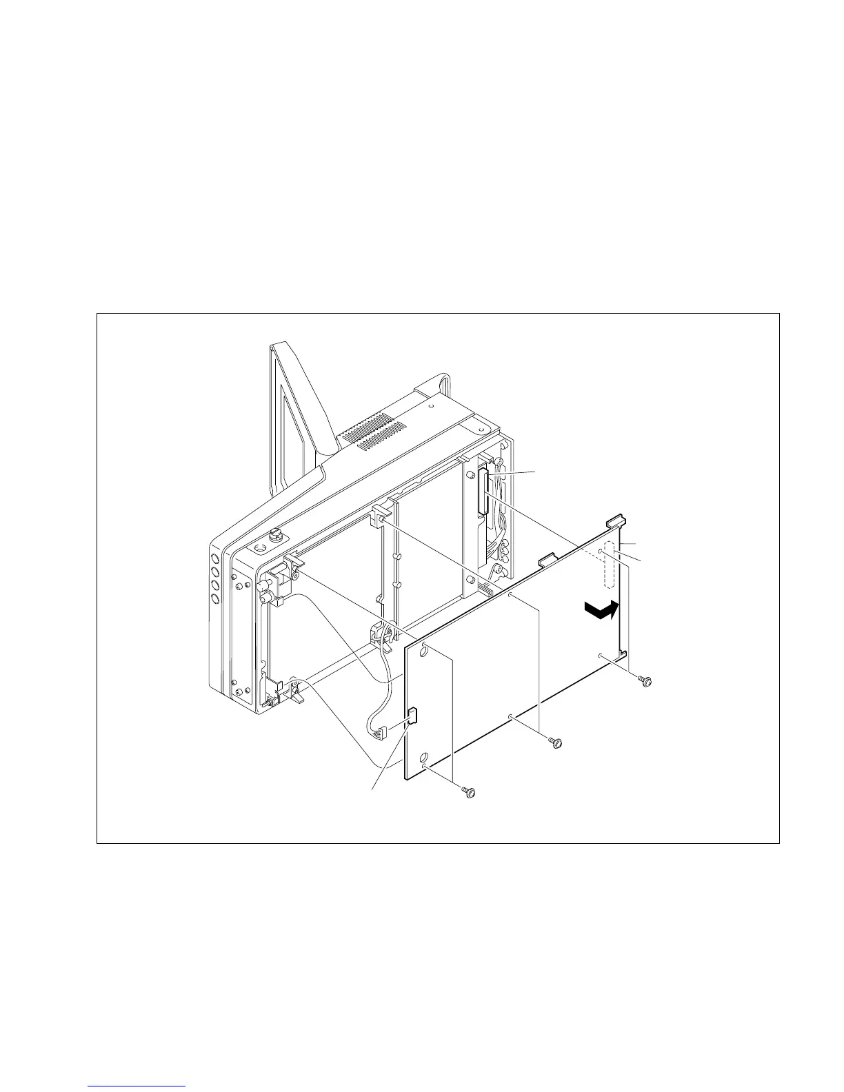
1-8-2. DM-121 Board
1. Remove the bottom plate. (Refer to Section 1-6-4.)
2. Remove the six screws of the DM-121 board.
3. Disconnect the harness from the connector CN1.
4. Grasp the board by the edge toward the connector panel, and then remove it in the direction of the
arrow.
5. Reinstall the DM-121 board in the order of steps 3, 4, 2 and 1.
n
Ensure that the CN101 of the DM-121 board firmly connects to the CN101 of the MB-838 board
before securing the DM-121 board using the screws.
1-8. Disconnecting/Reconnecting the Printed Circuit Boards
PWH2.6 x 5
PWH2.6 x 5
PWH2.6 x 5
CN1
CN101 of MB-838 board
CN101
DM-121 board